1 產品介紹
AFE‑R750 採用 ASR‑A701 作為其主機板。
本文件將說明如何在 JetPack 6.1 環境下使用 AFE-R750/ASR-A701。
1-1 產品特色
- AMR AI 控制器,AI 運算能力最高可達 275 TOPS
- AMR 專用 I/O:4 組 GbE、2 組 COM、DIO、CANFD
- 支援相機、LiDAR、IMU 等感測器連接
- 支援 Ubuntu 22.04、JetPack 6.1 SDK
- 符合 IEC 61000-6-4 重工業認證
- 支援 Advantech Robotic Suite
1-2 官方網站
2 硬體介面介紹
2-1 外觀尺寸
- AFE-R750-M 系列 (Orin NX)
- AFE-R750-X 系列 (AGX Orin)
- ASR-A701 (mini-ITX)
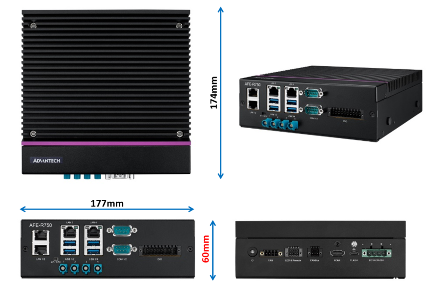
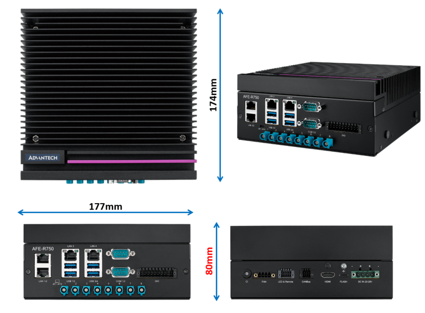
ASR-A701 為 mini-ITX 尺寸,170mm x 170mm。
2-2 開關與跳線
請參考以下圖片了解開關與跳線的設定方式。
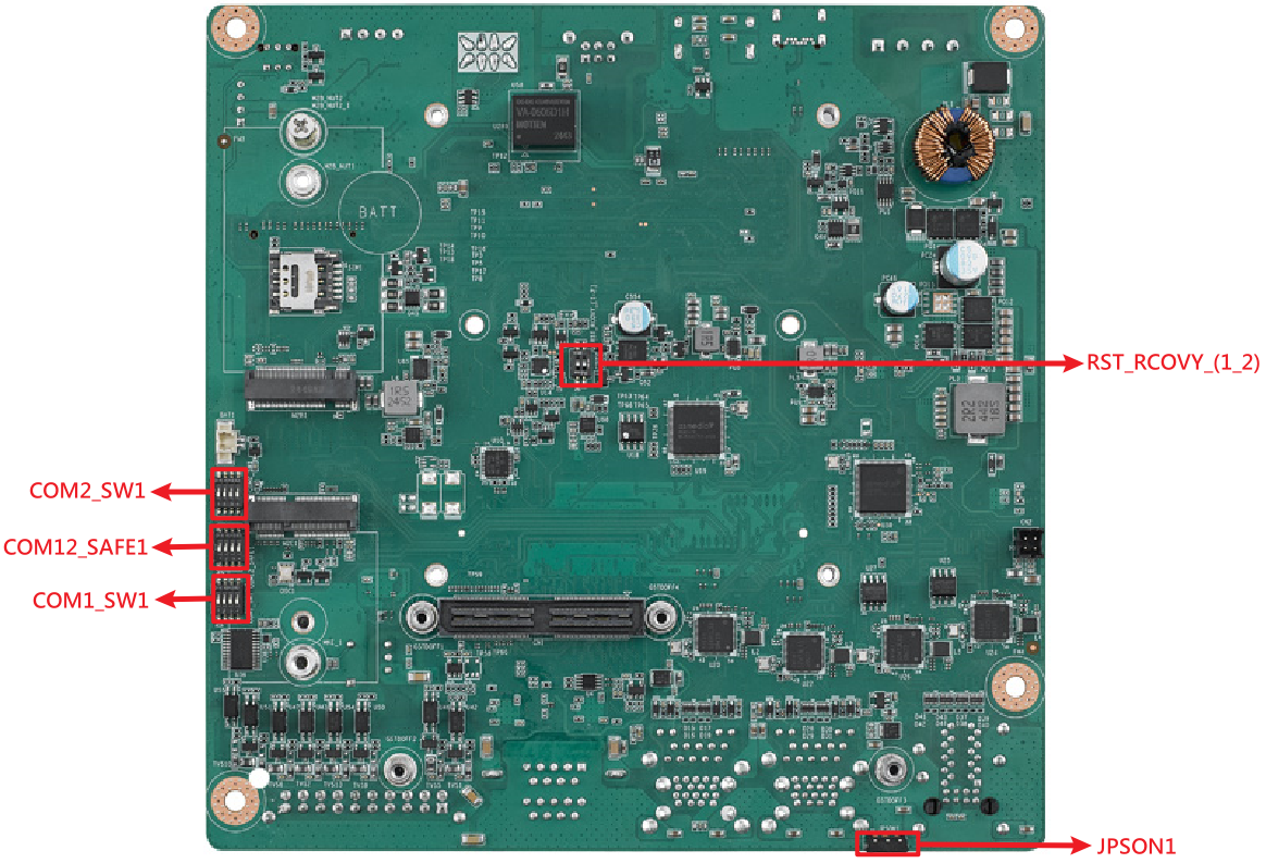
| 名稱 | 說明 |
|---|---|
| RST_RCOVY_(1_2) | 系統重置與系統映像檔復原,用於刷寫映像檔時使用。 |
| COM12_SAFE1 | 啟用或停用 RS-422/RS-485 的容錯安全(fail safe)功能。 |
| COM1_SW1 | 用於選擇 COM1 的 RS-232/RS-422/RS-485 模式,詳細說明請參見 COM 章節。 |
| COM2_SW1 | 用於選擇 COM2 的 RS-232/RS-422/RS-485 模式,詳細說明請參見 COM 章節。 |
| JPSON1 | 用於選擇 AT 或 ATX 模式的開關。 |
2-3 連接器介紹
請參考以下圖片了解各 IO 連接器的位置,關於接腳定義的詳細資訊請參考 AFE-R750 使用者手冊。
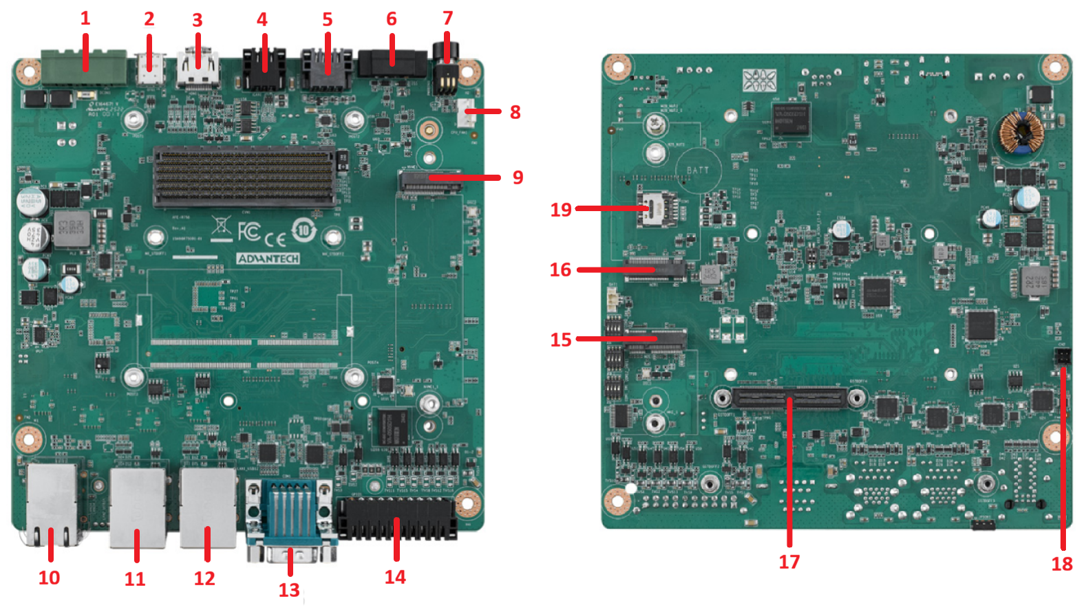
| 項次 | 名稱 | 說明 |
|---|---|---|
| 1 | DCIN1 | DC IN 電源連接器 |
| 2 | OTG1 | Type-C(僅供刷寫映像檔使用) |
| 3 | HDMI1 | HDMI 顯示介面 |
| 4 | CAN1 | CAN BUS 介面 |
| 5 | REMOTE1 | 遙控連接器 |
| 6 | SYS_FAN1 | 機殼風扇連接器 |
| 7 | PWRBTN1 | 電源開關 |
| 8 | CPU_FAN1 | 內部風扇連接器 |
| 9 | NVME1 | M.2 M-Key 連接器 |
| 10 | LAN1/2 | 2 * 乙太網路 RJ-45 連接器 |
| 11 | LAN3_USB12 | RJ-45 與 2 * USB 3.2 Gen2 連接器 |
| 12 | LAN4_USB34 | RJ-45 與 2 * USB 3.2 Gen2 連接器 |
| 13 | COM12 | 2 * COM DP9 連接器 |
| 14 | GPIO1 | GPIO 16-bit 隔離連接器 |
| 15 | M2E1 | M.2 E-Key 連接器 |
| 16 | M2B1 | M.2 B-Key 連接器 |
| 17 | CN1 | GMSL MIPI-120 pins 連接器 |
| 18 | CN2 | GMSL 板電源連接器 |
| 19 | SIM1 | SIM 卡座 |
3 作業系統
3-1 映像檔下載
| 映像檔版本 | 發布日期 | 映像檔下載 | BSP 下載標籤 | 備註 |
|---|---|---|---|---|
| JetPack6.2_v8_RT | 2026-06-17 | Onedrive | afer750a1_ubuntu22.04-jp6.2_v8.0.0_kernel-5.15.148_agx-orin+orin-nx.xml | 內建即時(real-time)核心 |
| JetPack6.1_v7 | 2026-02-11 | Dropbox | afer750a1_ubuntu22.04-jp6.1_v7.0.0_kernel-5.15.148_agx-orin+orin-nx.xml | 修正 orin nx com 順序 修正 bmi088 GMSL 預先安裝 SUSI 設定 wifi179 170 安裝腳本 |
| JetPack6.1_v4 | 2025/09/23 | Dropbox | afer750a1_ubuntu22.04-jp6.1_v4.0.0_kernel-5.15.148_agx-orin+orin-nx.xml | 修正自動更新版本問題 |
3-2 刷寫映像檔
請參考線上文件 Flash JetPack 6.X to AFE-R750 以取得如何將 JetPack 刷寫至 AFE-R750 的詳細說明。
3-3 BSP 下載
請參考以下線上文件取得如何下載與建置 AFE-R750 BSP 的詳細說明。
JetPack 6.2 BSP
JetPack 6.1 BSP
4 操作方式
4-1 帳號與密碼
AFE-R750 的預設帳號與密碼皆為 ubuntu。
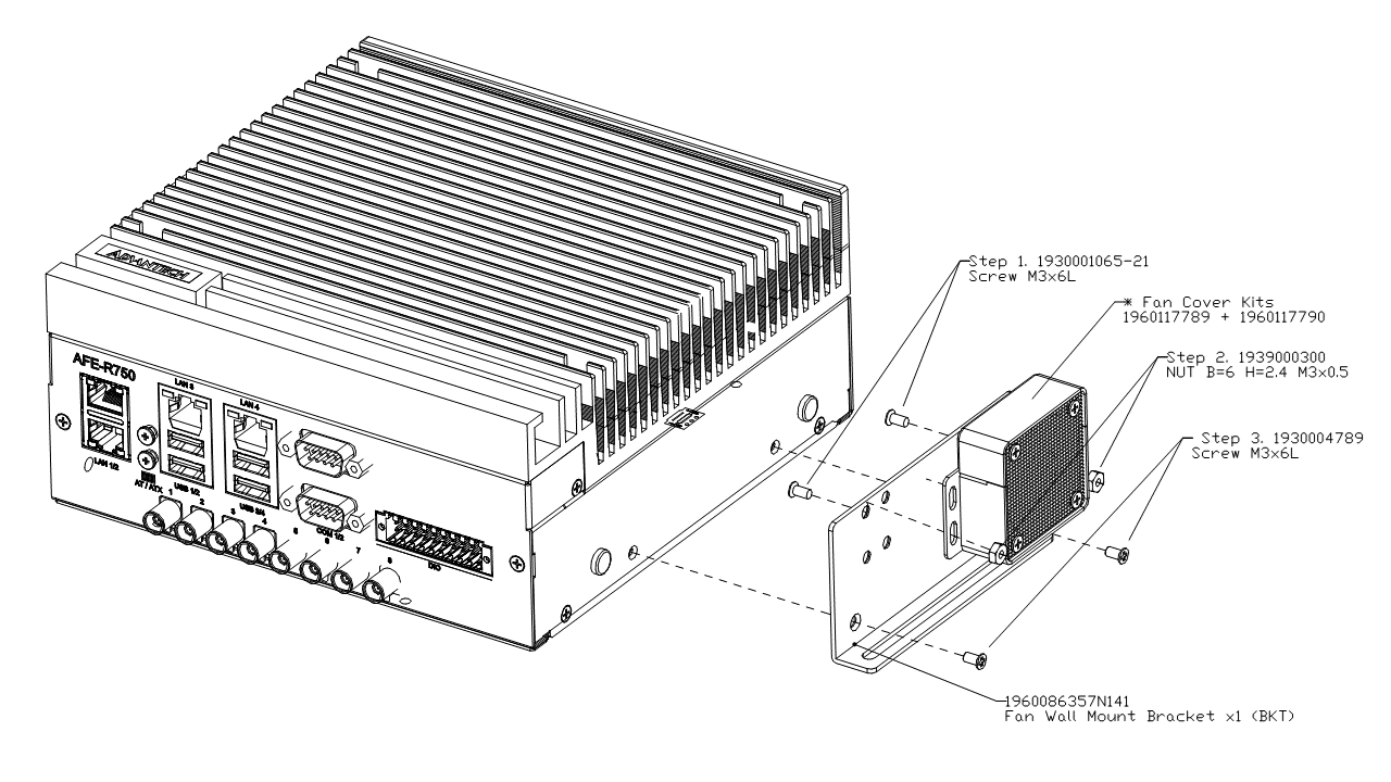
4-2 風扇套件
風扇套件產品編號為 AMK-A0057,適用於以 MAXN 功耗模式運作的 AGX Orin。
風扇套件安裝方式如下圖所示,智慧風扇設定也一併列於下表中。
| 溫度 (℃) | 風扇 PWM 值 | 風扇轉速值 (RPM) |
|---|---|---|
| 0 | 66 | 3123 |
| 39 | 66 | 3123 |
| 63 | 77 | 3600 |
| 86 | 212 | 10000 |
| 92 | 212 | 10000 |
| 93 | 255 | 12000 |
| 105 | 255 | 12000 |
4-3 控制器區域網路 (CAN)
AFE-R750 提供 1 組(Orin NX)或 2 組(AGX Orin)CAN FD,最高支援 3.7M 資料傳輸速率,詳細資訊可參考 NV 開發者指南。
CAN 接腳定義如下圖所示,請參考以下指令使用 CAN 匯流排。
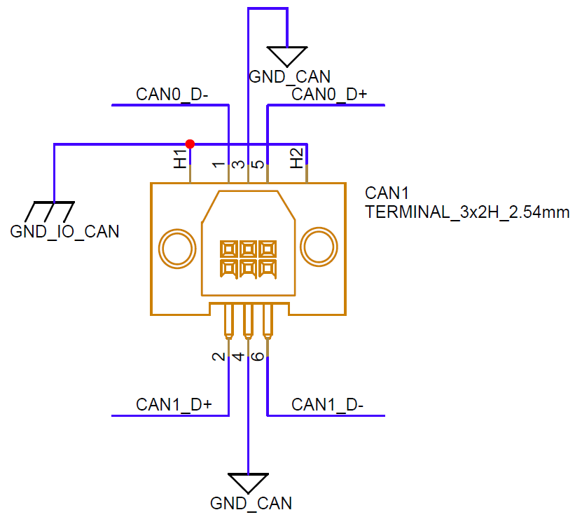
插入 CAN 相關模組,並將 CAN0 與 CAN1 的傳輸速率設定為 1Mbps。
$ sudo modprobe can
$ sudo modprobe can-dev
$ sudo modprobe mttcan
$ sudo ip link set can0 down
$ sudo ip link set can1 down
$ sudo ip link set can0 type up can bitrate 1000000 dbitrate 1000000 fd on
$ sudo ip link set can1 type up can bitrate 1000000 dbitrate 1000000 fd on
使用 can-utils 透過 CAN 埠 1 接收 CAN 訊息。
$ sudo candump can1
在另一個終端機上使用 can-utils 透過 CAN 埠 0 傳送 CAN 訊息。
$ sudo cansend can0 123#12341234
4-4 可信賴平台模組 (TPM)
AFE-R750 提供 TPM 2.0 模組以強化系統安全性。請先透過 apt 指令安裝 tpm2-tools,再參考以下指令使用 TPM。
$ sudo apt install -y tpm2-tools
$ sudo -s
4-4-1 檔案加密與解密
- 建立一個平台層級主金鑰,並將內容儲存至 platform_primary.ctx 檔案中。
# tpm2_createprimary -C p -c platform_primary.ctx
- 基於平台主金鑰,使用 RSA2048 加密方式產生一組公開金鑰與私密金鑰。
# tpm2_create -C platform_primary.ctx -G rsa2048 -u key.pub -r key.priv
- 將平台主金鑰載入 TPM,並將內容儲存至 key.ctx 檔案中。
key.pub 可以分享給他人用於加密,而 key.priv 應妥善保密。
# tpm2_load -C platform_primary.ctx -u key.pub -r key.priv -c key.ctx
- 在其他裝置上,使用 key.pub 將 msg.dat 中的訊息加密為 msg.enc。
# tpm2_loadexternal -C n -u key.pub -c pub.ctx
# tpm2_rsaencrypt -c pub.ctx -o msg.enc msg.dat
- 將 msg.enc 檔案帶回 AFE-R750,並使用 key.ctx 解密訊息。
解密後的訊息將儲存至 msg.ptext 檔案中。
# tpm2_rsadecrypt -c key.ctx -o msg.ptext msg.enc
# cat msg.ptext
4-4-2 非揮發性空間讀寫
- 定義一個非揮發性空間,其 ID 為 0x1500031,大小為 2048 位元組,權限為擁有者可讀/寫、政策寫入。
# tpm2_nvdefine -Q 0x1500031 -C o -s 32 -a "ownerread|policywrite|ownerwrite"
- 將 msg.dat 檔案中的資料寫入所定義的非揮發性空間,msg.dat 大小須小於 2048 位元組。
# tpm2_nvwrite -Q 0x1500031 -C o -i msg.dat
- 從所定義的非揮發性空間中讀回資料,儲存至 read.data 檔案中。
# tpm2_nvread -Q 0x1500031 -C o -s 32 -o read.data
# cat read.data
4-5 數位輸入輸出 (DIO)
AFE-R750 提供 8 位元 DI 與 8 位元 DO,所有 DO 皆為開洩極(open-drain)硬體設計,需要外部電源與提升電阻配合使用。
DIO 接腳定義如下圖所示,請參考以下指令了解 DIO 的使用方式及硬體連接範例。
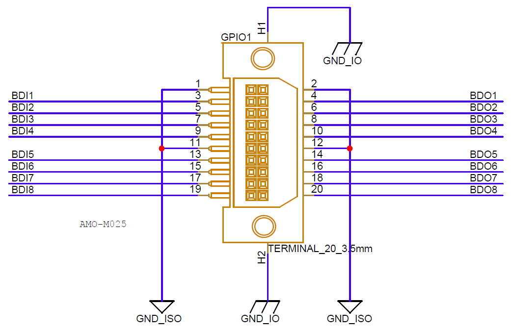
共 16 位元 DIO 屬於 gpiochip2 群組,line 0 到 7 為 DI,line 8 到 15 為 DO。
$ sudo gpioinfo
使用 gpioget 指令搭配晶片編號與線路編號讀取 DIO 電位,例如讀取 DI0 電位。
$ sudo gpioget gpiochip2 0
使用 gpioset 指令搭配模式、晶片編號、線路編號與電位設定 DO 電位,例如將 DO0 設為高電位。
$ gpioset --mode=wait gpiochip2 8=1
DIO 硬體連接範例如下所示。
- 當 DO0 被設為低電位時,MOSFET 會導通,電流將流經 LED。
- 當 DO0 被設為高電位時,MOSFET 會截止,LED 將熄滅。
- 當開關被按下時,DI0 可讀取到低電位。
- 當開關被釋放時,DI0 會透過提升電阻讀取到高電位。
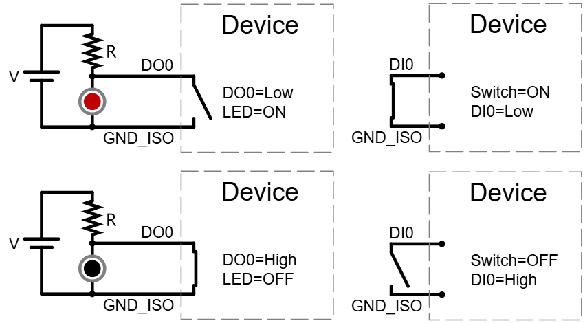
注意:外部電源電壓 V 允許範圍為 5 到 28V,流入 DO 的電流必須小於 1A。
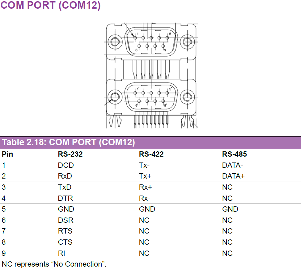
4-6 通訊埠 (COM)
COM 接腳定義如下圖所示。
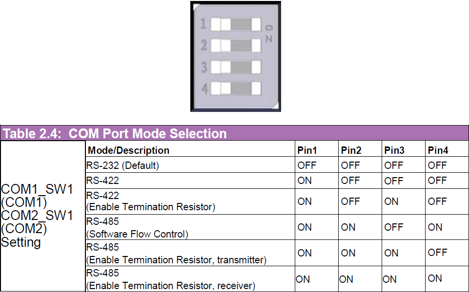
模式選擇方式如下圖所示。
| SoC | COM1(軟體控制接腳) | COM2(軟體控制接腳) |
|---|---|---|
| AGX Orin | /dev/ttyTHS1 (112) | /dev/ttyTHS2 (129) |
| Orin NX | /dev/ttyTHS2 (120) | /dev/ttyTHS1 (112) |
- RS-232
- RS-422
- RS-485
在 RS-232 模式下,將 COM1 的 Tx 連接至 COM2 的 Rx,Rx 連接至 COM2 的 Tx,並將 COM_SW1 全部 4 個接腳都設為 OFF。
以下指令示範將資料從 ttyTHS1 傳送至 ttyTHS2,使用 echo 指令進行傳送、cat 指令進行接收。
第一個終端機(/dev/ttyTHS2 接收資料):
$ sudo su
# stty -F /dev/ttyTHS1 speed 115200 raw -echo
# stty -F /dev/ttyTHS2 speed 115200 raw -echo
# cat /dev/ttyTHS2

第二個終端機(/dev/ttyTHS1 傳送資料):
$ sudo su
# echo "1234" > /dev/ttyTHS1
在 RS-422 模式下,將 COM1 的 Tx+ 連接至 COM2 的 Rx+,Tx- 連接至 COM2 的 Rx-,Rx+ 連接至 COM2 的 Tx+,Rx- 連接至 COM2 的 Tx-,並將 COM_SW1 的第 1 個接腳設為 ON,其餘設為 OFF。
以下指令示範將資料從 ttyTHS1 傳送至 ttyTHS2,使用 echo 指令進行傳送、cat 指令進行接收。
第一個終端機(/dev/ttyTHS2 接收資料):
$ sudo su
# stty -F /dev/ttyTHS1 speed 115200 raw -echo
# stty -F /dev/ttyTHS2 speed 115200 raw -echo
# cat /dev/ttyTHS2

第二個終端機(/dev/ttyTHS1 傳送資料):
$ sudo su
# echo "1234" > /dev/ttyTHS1
在 RS-485 模式下,將 COM1 的 data- 連接至 COM2 的 data-,data+ 連接至 COM2 的 data+。
若 COM_SW1 設為傳送端(transmitter),則無法接收資料;設為接收端(receiver),則無法傳送資料。
若設為軟體控制,則每個 COM 埠都有各自的 GPIO 接腳用於控制流量控制,傳送資料前須先將該 GPIO 接腳設為高電位。
第一個終端機(/dev/ttyTHS2 接收資料):
$ sudo su
# stty -F /dev/ttyTHS1 speed 115200 raw -echo
# stty -F /dev/ttyTHS2 speed 115200 raw -echo
# cat /dev/ttyTHS2

第二個終端機(/dev/ttyTHS1 傳送資料):
$ sudo su
# gpioset --mode=wait gpiochip0 112=1
# echo "1234" > /dev/ttyTHS1
# kill $!
4-7 慣性測量單元 (IMU)
AFE-R750 支援兩種 IMU 感測器,一種是板載的 BMI088,另一種是選配的 MTi-3。
為了將 IMU 資料接入 ROS2,我們需要先安裝相關的 SDK 與套件包。
$ sudo apt install -y ros-humble-rviz2 ros-humble-imu-tools ros-humble-imu-filter-madgwick pre-commit ros-humble-nmea-msgs ros-humble-mavros-msgs
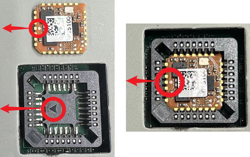
4-7-1 BMI088
- JetPack 6.1 20260211 (V7)
- JetPack 6.1 20250923 (V4)
BMI088 驅動程式已預設整合於 JetPack 6.1 中,請參考以下指令從 BMI088 取得加速度計與陀螺儀資料。
$ sudo su
# /usr/local/bin/IMU/iio_generic_buffer -a -c 10 --device-name accelerometer -g
# /usr/local/bin/IMU/iio_generic_buffer -a -c 10 --device-name gyroscope -g
確認 BMI088 正常運作後,我們可以安裝其 ROS2 套件包,在 rviz2 中將資料視覺化。
$ wget https://iedgeblob.blob.core.windows.net/robotic-suite-public/sensor/xsens_bmi088-node-1.0.0-humble-imx8.run
$ chmod +x xsens_bmi088-node-1.0.0-humble-imx8.run
$ sudo ./xsens_bmi088-node-1.0.0-humble-imx8.run
$ source /opt/ros/humble/setup.bash
$ source /usr/local/Advantech/ros/humble/sensor_extension/ros2-imu-bmi088/install/setup.bash
$ sudo chown -R ubuntu /dev/iio:device*
$ sudo chown -R ubuntu /sys/devices/platform/bus@0/c240000.i2c/i2c-1/1-0068/iio:device*
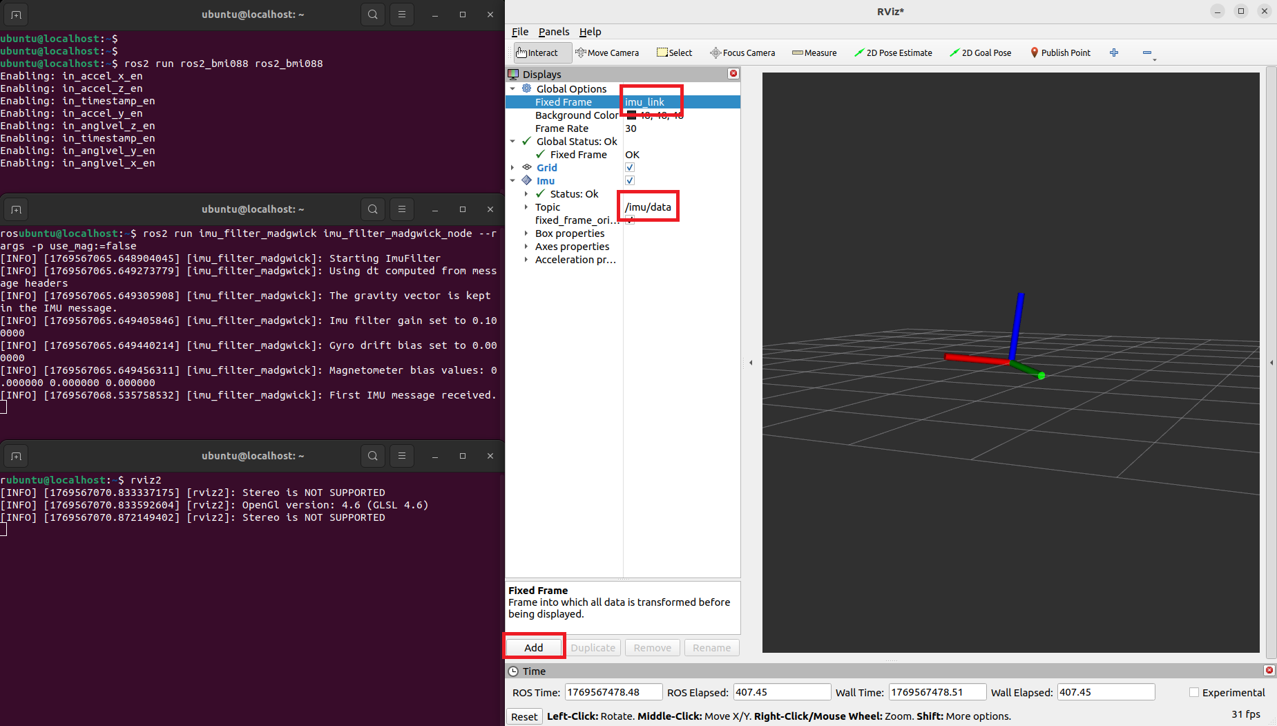
$ ros2 run ros2_bmi088 ros2_bmi088 &
$ ros2 run imu_filter_madgwick imu_filter_madgwick_node --ros-args -p use_mag:=false &
$ rviz2
在 rviz2 中點擊 Add,選擇 By topic,加入 /imu/data 主題,並將 Fixed Frame 改為 imu_link,即可將 IMU 資料視覺化。
V4 之前的映像檔並未整合 BMI088 驅動程式,如需使用 BMI088,請重新刷寫為 JetPack 6.1 V7 映像檔。
4-7-2 MTi-3
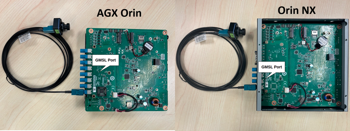
MTi-3 IMU 感測器安裝於料號為 AFE-RM04-4PA1 與 AFE-RM04-8PA1 的 GMSL 板上,但僅支援 AFE-R750-X 系列(AGX Orin 模組)。
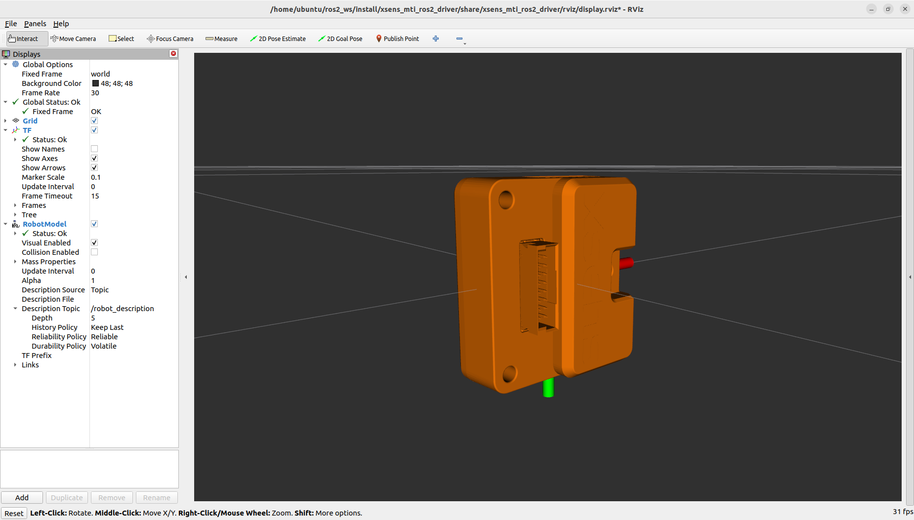
安裝感測器後,請依照以下步驟在 rviz2 中將資料視覺化。更多細節可參考 官方 Github。
$ cd ~
$ git clone --branch ros2 https://github.com/xsenssupport/Xsens_MTi_ROS_Driver_and_Ntrip_Client.git
$ mv Xsens_MTi_ROS_Driver_and_Ntrip_Client ros2_ws
$ cd ~/ros2_ws
$ colcon build --symlink-install
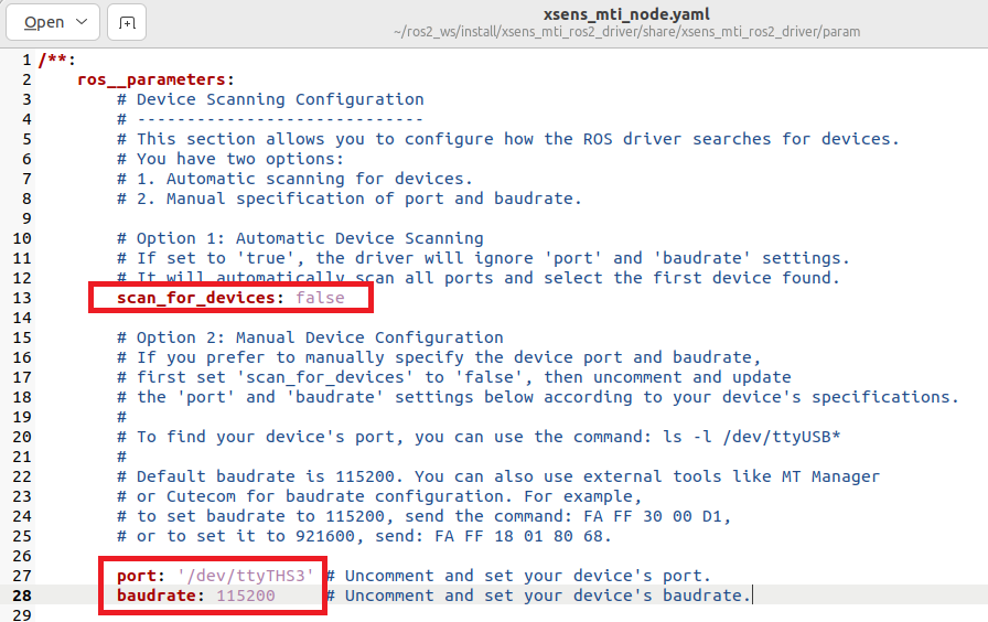
編輯 ~/ros2_ws/install/xsens_mti_ros2_driver/share/xsens_mti_ros2_driver/param/xsens_mti_node.yaml,將 scan_for_devices 設為 false,port 設為 /dev/ttyTHS3,baudrate 設為 115200。
$ sudo chmod 777 /dev/ttyTHS3
$ sudo stty -F /dev/ttyTHS3 speed 115200 -echo
$ source /opt/ros/humble/setup.bash
$ source ~/ros2_ws/install/setup.bash
$ ros2 launch xsens_mti_ros2_driver display.launch.py
4-8 Wi-Fi 與藍牙
AFE-R750 支援兩種 Wi-Fi 模組,一種是 AIW-170,另一種是 EWM-W179。
兩種模組的驅動程式皆已整合至 AFE-R750 映像檔中。
同一時間只能安裝一種 WiFi 驅動程式,安裝新的驅動程式會取代舊的驅動程式。
4-8-1 AIW-170
- JetPack 6.1 20260211 (V7)
- JetPack 6.1 20250923 (V4)
只需執行以下指令一次,AIW-170 驅動程式將於系統開機後自動安裝並載入。
$ cd /usr/local/bin/AIW-170
$ sudo bash install_aiw-170.sh
$ sudo reboot
每次系統開機時執行以下指令以載入 AIW-170 驅動程式。
$ cd /usr/local/bin/AIW-170
$ sudo insmod btbcm.ko
$ sudo insmod btintel.ko
$ sudo insmod btqca.ko
$ sudo insmod btrtl.ko
$ sudo insmod btusb.ko
$ sudo modprobe cfg80211
$ sudo insmod wlan_cnss_core_pcie.ko
$ sudo insmod wlan.ko
4-8-2 EWM-W179
- JetPack 6.1 20260211 (V7)
- JetPack 6.1 20250923 (V4)
只需執行以下指令一次,EWM-W179 驅動程式將於系統開機後自動安裝並載入。
$ cd /usr/local/bin/EWM-W179
$ sudo bash install_ewm-w179.sh
$ sudo reboot
每次系統開機時執行以下指令以載入 EWM-W179 驅動程式。
$ cd /usr/local/bin/EWM-W179
$ sudo modprobe cfg80211
$ sudo insmod rtk_btusb.ko
$ sudo insmod 8852be.ko
4-9 相機解決方案
AFE-R750 已將 oToBrite oToCAM222 驅動程式整合至映像檔中,請參考以下指令使用 oToCAM222。
AFE-R750 也支援其他 GMSL 相機,例如 Orbbec Gemini-335LG 與 StereoLabs ZedX,詳細說明請參考 AFE-R750 GMSL 驅動程式。
注意:由於驅動程式與即時核心不相容,搭載即時核心的 Jetpack 6.2 不支援 GMSL 相機,如需使用 GMSL 相機請使用 Jetpack 6.1 映像檔。
根據 SoC 執行內建腳本,在系統中設定 GMSL 相機的裝置樹(device tree)。此步驟只需執行一次,執行後系統將會重新開機。
$ cd /usr/local/bin/otocam
$ sudo ./set_otocam_agxorin_64g.sh
$ sudo ./set_otocam_agxorin_32g.sh
$ sudo ./set_otocam_orinnx.sh
AFE-R750 重新開機後,執行插入驅動程式的腳本與啟用相機的腳本,視訊畫面即會顯示出來。
$ cd /home/ubuntu
$ sudo ./insmod-otocam.sh
$ sudo ./enable-otocamera.sh
4-10 PPS 時間同步
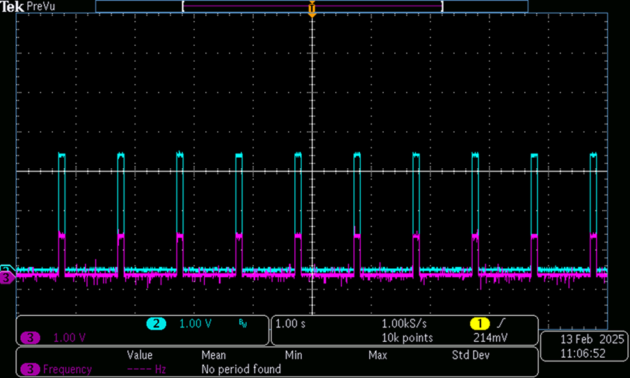
AFE-R750 可安裝 AIW-210XU-001 GNSS 模組以取得 PPS(每秒脈衝,pulse per second)訊號,用於應用程式的時間同步,PPS 訊號如下圖所示。
請參考以下指令安裝 GPS 與 PPS 時間同步所需的相關工具程式。
$ sudo apt install -y gpsd gpsd-clients chrony
$ sudo echo -e START_DAEMON="true""\n"DEVICES="/dev/ttyACM0 /dev/pps0""\n"GPSD_OPTIONS="-n""\n"BAUDRATE="9600" > /etc/default/gpsd
$ sudo systemctl restart gpsd
$ sudo echo -e refclock SHM 0 refid NMEA offset 0.9999 delay 0.2 noselect"\n"refclock PPS /dev/pps0 lock NMEA refid PPS prefer"\n"makestep 0.001 10 > /etc/chrony
$ sudo systemctl restart chrony
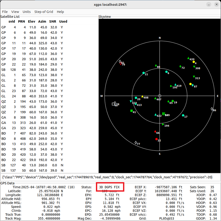
將 GPS 天線放置於戶外,並開啟 xgps 工具程式檢查 GPS 狀態,直到狀態顯示為 3D fixed。
檢查 chrony 的時間來源,確認 PPS 已被用作時間來源;一旦時間偏差超過 1ms 的門檻,系統時間將與 PPS 時間同步。
$ watch -n 0.1 chronyc sources