1 Product Introduction
The AFE‑R750 is using the ASR‑A701 as its motherboard.
This document will share how to use AFE-R750/ASR-A701 with JetPack 6.1.
| Model Name | AFE-R750-X2A1U | AFE-R750-X1A1U | AFE-R750-M1A1U |
|---|---|---|---|
| SoC | AGX Orin 32G | AGX Orin 64G | Orin NX 16G |
| AI Computing Power | 275 TOPS | 200 TOPS | 100 TOPS |
| Memory | 64 GB | 32GB | 16GB |
| OS Storage | 64GB eMMC or NVMe | 64GB eMMC or NVMe | NVMe only |
| Operating System | Ubuntu 22.04 JetPack 6.1 | ||
1-1 Product Features
- AMR AI Controller Board up to 275 TOPS AI computing
- Dedicated I/Os for AMR: 4xGbE, 2xCOM, DIO, CANFD
- Sensor connection for camera, LiDAR, IMU...etc
- Supports Ubuntu 22.04, JetPack 6.1SDK
- IEC 61000-6-4 Heavy Industry Certificate
- Supports Advantech Robotic Suite
1-2 Official Website
2 Mechanical and Environmental
2-1 Layout and Sizes
- AFE-R750-X series (AGX Orin)
- AFE-R750-M series (Orin NX)
- ASR-A701 (mini-ITX)


2-2 Thermal Solution
Fan kit Product Number is AMK-A0057, which is used for AGX Orin 64G in MAXN power mode.
The fan kit installation is shown as below. The smart fan setting is also provided as following table.
Note: The "Caution - Hot surface. Do Not Touch" warning is a default setting from NVIDIA. User can adjust this setting by following the instructions in official document.
https://docs.nvidia.com/jetson/archives/r36.4.3/DeveloperGuide/SD/PlatformPowerAndPerformance/JetsonOrinNanoSeriesJetsonOrinNxSeriesAndJetsonAgxOrinSeries.html#configuring-a-thermal-zone-using-the-device-tree

| Temperature (℃) | Fan PWM Value | Fan RPM Value |
|---|---|---|
| 0 | 66 | 3123 |
| 39 | 66 | 3123 |
| 63 | 77 | 3600 |
| 86 | 212 | 10000 |
| 92 | 212 | 10000 |
| 93 | 255 | 12000 |
| 105 | 255 | 12000 |
3 Hardware Interface Introduction
3-1 Switch and Jumper
Please refer to the following images for the switch and jumper settings.
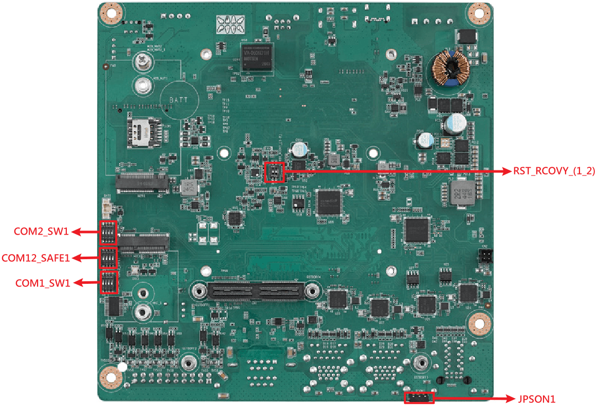
| Name | Description |
|---|---|
| RST_RCOVY_(1_2) | System reset and system image recovery, be used in flashing image. |
| COM12_SAFE1 | Enable or disable fail safe function for RS-422/RS-485. |
| COM1_SW1 | Switch for selecting COM1 RS-232/RS-422/RS-485 mode, described detailed in COM section. |
| COM2_SW1 | Switch for selecting COM2 RS-232/RS-422/RS-485 mode, described detailed in COM section. |
| JPSON1 | Switch for selecting AT or ATX mode. |
3-2 Connector Introduction
Please refer to the following images for the IO connectors, more details about the pin defination can be found in the AFE-R750 User Manual.

| Item | Name | Description |
|---|---|---|
| 1 | DCIN1 | DC IN power connector |
| 2 | OTG1 | Type-C (flash image only) |
| 3 | HDMI1 | HDMI display |
| 4 | CAN1 | CAN BUS interface |
| 5 | REMOTE1 | Remote connector |
| 6 | SYS_FAN1 | Chassis FAN connector |
| 7 | PWRBTN1 | Power button |
| 8 | CPU_FAN1 | Internal FAN connector |
| 9 | NVME1 | M.2 M-Key connector |
| 10 | LAN1/2 | 2 * Ethernet RJ-45 connector |
| 11 | LAN3_USB12 | RJ-45 & 2 * USB 3.2 Gen2 connector |
| 12 | LAN4_USB34 | RJ-45 & 2 * USB 3.2 Gen2 connector |
| 13 | COM12 | 2 * COM DP9 connector |
| 14 | GPIO1 | GPIO 16-bit isolation connector |
| 15 | M2E1 | M.2 E-Key connector |
| 16 | M2B1 | M.2 B-Key connector |
| 17 | CN1 | GMSL MIPI-120 pins connector |
| 18 | CN2 | GMSL board power connector |
| 19 | SIM1 | SIM card holder |
4 Operating System
4-1 Image Release Note
- JetPack 6.2
- JetPack 6.1
| Image Version | Release Date | Image Download | BSP Download Tag | Comment |
|---|---|---|---|---|
| JetPack6.2_v8_RT | 2026-06-17 | Onedrive | afer750a1_ubuntu22.04-jp6.2_v8.0.0_kernel-5.15.148_agx-orin+orin-nx.xml | built-in real-time kernel |
| Image Version | Release Date | Image Download | BSP Download Tag | Comment |
|---|---|---|---|---|
| JetPack6.1_v7 | 2026-02-11 | Dropbox | afer750a1_ubuntu22.04-jp6.1_v7.0.0_kernel-5.15.148_agx-orin+orin-nx.xml | fix orin nx com order fix bmi088 GMSL preinstall SUSI set wifi179 170 install script |
| JetPack6.1_v4 | 2025-09-23 | Dropbox | afer750a1_ubuntu22.04-jp6.1_v4.0.0_kernel-5.15.148_agx-orin+orin-nx.xml | Fixed automatic update version issue |
4-2 Flashing Image
Please refer to the online document Flash JetPack 6.X to AFE-R750 for detailed instructions on how to flash the JetPack to the AFE-R750.
4-3 BSP Download
Please refer to the online document for detailed instructions on how to download and build the BSP for the AFE-R750.
JetPack 6.2 BSP
JetPack 6.1 BSP (GMSL cameras are available, please refer to Sections 5-8 for details)
5 Operating Method
5-1 Account and Password
The default account and password for AFE-R750 are ubuntu.
User can run the following commands to change the default root and ubuntu password.
$ sudo passwd root
$ sudo passwd ubuntu
5-2 Controller Area Network (CAN)
AFE-R750 provides 1(Orin NX) or 2(AGX Orin) CAN FD which support up to 3.7M data bitrate, more information could refer to NV Developer Guide.
The CAN pin definition is shown as below. Please refer to the following commands for using CAN bus.

Insert the CAN related modules and set up the CAN0 and CAN1 bitrate to 1Mbps.
$ sudo modprobe can
$ sudo modprobe can-dev
$ sudo modprobe mttcan
$ sudo ip link set can0 down
$ sudo ip link set can1 down
$ sudo ip link set can0 up type can bitrate 1000000 dbitrate 1000000 fd on
$ sudo ip link set can1 up type can bitrate 1000000 dbitrate 1000000 fd on
CAN port 1 receives CAN message by using can-utils.
$ sudo candump can1CAN port 0 transmits CAN message by using can-utils on another terminal.
$ sudo cansend can0 123#123412345-3 Remote Control and Debug port
REMOTE1 connector let users control the AFE-R750 power status, and get the debug log from the system via RS-232.
The pin definition is shown as below.
If PWRBTN# short to GND, the system will get power on signal. If SYS_RST_IN_N short to GND, the system will get reset signal.
Connect the COM3_TXD and COM3_RXD to a RS-232 COM on host, host can get the debug log within 115200 baud rate from AFE-R750.

5-4 Communication Port (COM)
The COM pin definition is shown as below.
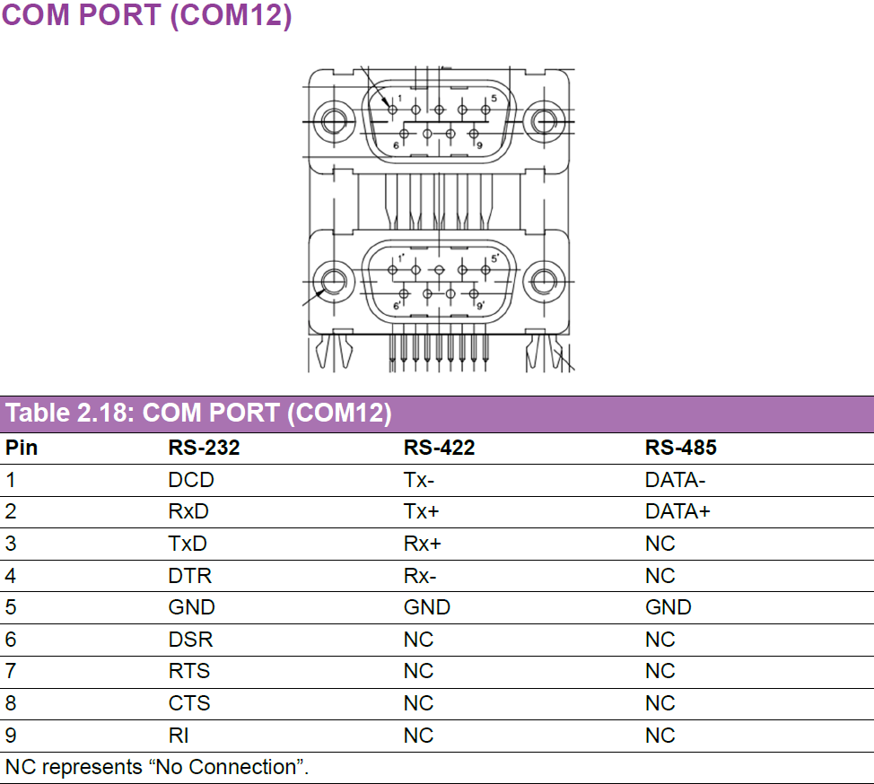
The mode selection is shown as below.
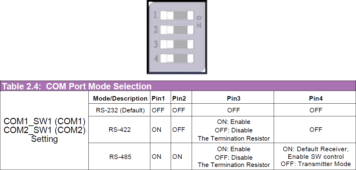
If SW1 Pin 4 is set to ON, RS-485 is receiving mode, it becomes transmitter mode once the flow control pin is pull-high.
| SoC | COM1 (Flow control pin for RS-485) | COM2 (Flow control pin for RS-485) |
|---|---|---|
| AGX Orin | /dev/ttyTHS1 (112 in gpiod) | /dev/ttyTHS2 (129 in gpiod) |
| Orin NX | /dev/ttyTHS2 (120 in gpiod) | /dev/ttyTHS1 (112 in gpiod) |
- RS-232
- RS-422
- RS-485
In RS-232 mode, connect COM1 Tx to COM2 Rx and Rx to COM2 Tx, and set COM_SW1 total 4 pins to OFF.
The following commands send data from ttyTHS1 to ttyTHS2, using the echo command for transmission and the cat command for reception.
First terminal (/dev/ttyTHS2 receive data):
$ sudo su
# stty -F /dev/ttyTHS1 115200 raw -echo
# stty -F /dev/ttyTHS2 115200 raw -echo
# cat /dev/ttyTHS2
Second terminal (/dev/ttyTHS1 send data):
$ sudo su
# echo "1234" > /dev/ttyTHS1
In RS-422 mode, connect COM1 Tx+ to COM2 Rx+, Tx- to COM2 Rx-, Rx+ to COM2 Tx+, Rx- to COM2 Tx-, and set COM_SW1 pin 1 to ON, others to OFF.
The following commands send data from ttyTHS1 to ttyTHS2, using the echo command for transmission and the cat command for reception.
First terminal (/dev/ttyTHS2 receive data):
$ sudo su
# stty -F /dev/ttyTHS1 115200 raw -echo
# stty -F /dev/ttyTHS2 115200 raw -echo
# cat /dev/ttyTHS2
Second terminal (/dev/ttyTHS1 send data):
$ sudo su
# echo "1234" > /dev/ttyTHS1
In RS-485 mode, connect COM1 data- to COM2 data-, data+ to COM2 data+.
If COM_SW1 is set to transmitter, it cannot receive data; set to receiver, it cannot send data.
If it is set to software control, each COM port has own GPIO pin to control flow control. Set the GPIO pin to high before sending data.
First terminal (/dev/ttyTHS2 receive data):
$ sudo su
# stty -F /dev/ttyTHS1 115200 raw -echo
# stty -F /dev/ttyTHS2 115200 raw -echo
# cat /dev/ttyTHS2
Second terminal (/dev/ttyTHS1 send data):
$ sudo su
# gpioset 0 112=1
# echo "1234" > /dev/ttyTHS1
# kill $!
5-5 Digital Input / Output (DIO)
AFE-R750 provides 8 bits DI and 8 bits DO, all DO are open-drain hardware design, it will require external power and pull-up resistor.
The DIO pin definition is shown as below. Please refer to the following commands for using DIO and hardware connection example.
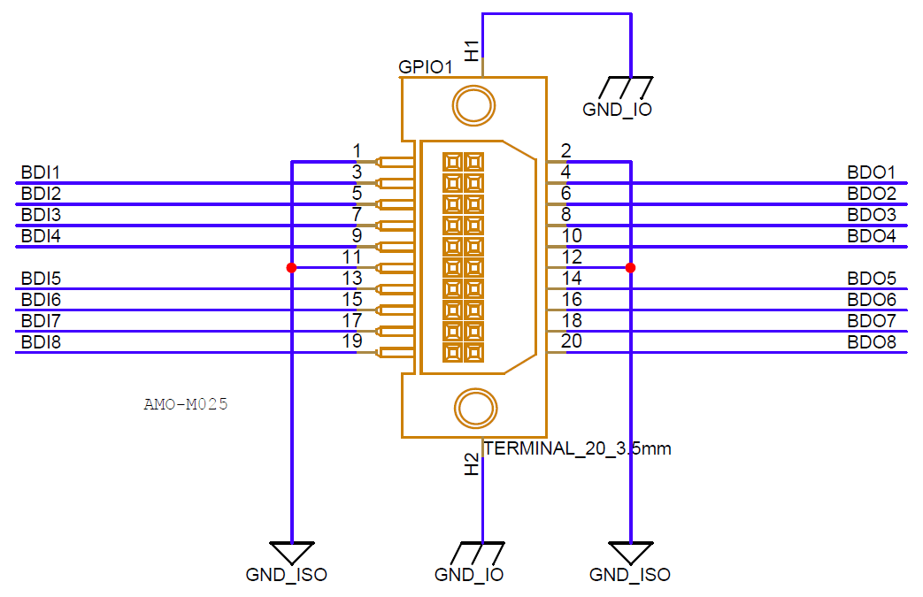
Total 16 bits DIO are in the gpiochip2 group, line 0 to 7 are DI and line 8 to 15 are DO.
$ sudo gpioinfoRead DI level by gpioget command with chip number and line number, for example, read DI0 level.
$ sudo gpioget 2 0Set DO level by gpioset command with mode, chip number, line number and level, for example, set DO0 to high level.
$ sudo gpioset 2 8=1Hardware connection example for DIO are shown as below.
- When DO0 be set to low, MOSFET will be opened, current will go through LED.
- When DO0 be set to high, MOSFET will be closed, LED will be off.
- If the switch is pressed, DI0 could read the low level.
- If the switch is released, DI0 will read high level through the pull-up resistor.

Notice: the external power supply V is allowed 5 to 28V, and the current entering DO must be less than 1A.
5-6 Wireless Communication Module
5-6-1 5G Module
AFE-R750 supports the AIW-357 (M.2 Key-B) 5G module. Insert the Nano-SIM before booting.
Follow the AIW-Tool User Guide to setup AIW-357 module, the AIW-Tool could be found at /usr/local/bin/AIW-357.
5-6-2 Wi-Fi and Bluetooth Module
AFE-R750 supports two Wi-Fi modules, one is AIW-170, the other is EWM-W179.
The drivers for both modules have been integrated into the AFE-R750 image.
Only one WiFi driver can be installed at a time. Installing a new one will replace the old one.
AIW-170
- JetPack 6.1 20260211 (V7)
- JetPack 6.1 20250923 (V4)
Run the following commands once, AIW-170 driver will be installed and loaded automatically after system boot up.
$ cd /usr/local/bin/AIW-170
$ sudo bash install_aiw-170.sh
$ sudo reboot
Run the following commands to load AIW-170 driver every system boot up.
$ cd /usr/local/bin/AIW-170
$ sudo insmod btbcm.ko
$ sudo insmod btintel.ko
$ sudo insmod btqca.ko
$ sudo insmod btrtl.ko
$ sudo insmod btusb.ko
$ sudo modprobe cfg80211
$ sudo insmod wlan_cnss_core_pcie.ko
$ sudo insmod wlan.ko
EWM-W179
- JetPack 6.1 20260211 (V7)
- JetPack 6.1 20250923 (V4)
Run the following commands once, EWM-W179 driver will be installed and loaded automatically after system boot up.
$ cd /usr/local/bin/EWM-W179
$ sudo bash install_ewm-w179.sh
$ sudo reboot
Run the following commands to load EWM-W179 driver every system boot up.
$ cd /usr/local/bin/EWM-W179
$ sudo modprobe cfg80211
$ sudo insmod rtk_btusb.ko
$ sudo insmod 8852be.ko
5-6-3 GPS and PPS Time Sync
AFE-R750 can install AIW-210XU-001 GNSS module to get PPS (pulse per second) for time synchronizing on application, PPS signal is shown as below.

Please refer to the following commands for installing GPS and time synchronzing related utility for PPS time synchronization.
$ sudo apt install -y gpsd gpsd-clients chrony
$ sudo echo -e START_DAEMON="true""\n"DEVICES="/dev/ttyACM0 /dev/pps0""\n"GPSD_OPTIONS="-n""\n"BAUDRATE="9600" > /etc/default/gpsd
$ sudo systemctl restart gpsd
$ sudo echo -e refclock SHM 0 refid NMEA offset 0.9999 delay 0.2 noselect"\n"refclock PPS /dev/pps0 lock NMEA refid PPS prefer"\n"makestep 0.001 10 > /etc/chrony
$ sudo systemctl restart chrony
Put the GPS antenna to outdoor, and open xgps utility to check GPS status until it is 3D fixed.

Check chrony sources to see PPS is used as time source, the system time will synchronize with PPS time once the deviation threshold of time is larger than 1ms.
$ watch -n 0.1 chronyc sources5-7 Inertial Measurement Unit (IMU)
AFE-R750 supports two IMU sensors, one is onboard BMI088, the other is MTi-3 which is optional.
In order to connect IMU data into ROS2, we need to install the related SDK and packages first.
$ sudo apt install -y ros-humble-rviz2 ros-humble-imu-tools ros-humble-imu-filter-madgwick pre-commit ros-humble-nmea-msgs ros-humble-mavros-msgs5-7-1 BMI088
- JetPack 6.1 20260211 (V7)
- JetPack 6.1 20250923 (V4)
BMI088 driver had been integrated in JetPack 6.1 by default, please refer to the following commands for getting accelerometer and gyroscope datas from BMI088.
$ sudo su
# /usr/local/bin/IMU/iio_generic_buffer -a -c 10 --device-name accelerometer -g
# /usr/local/bin/IMU/iio_generic_buffer -a -c 10 --device-name gyroscope -g
After checking BMI088 is working, we can install its ROS2 package to visualize the data in rviz2.
$ wget https://iedgeblob.blob.core.windows.net/robotic-suite-public/sensor/xsens_bmi088-node-1.0.0-humble-imx8.run
$ chmod +x xsens_bmi088-node-1.0.0-humble-imx8.run
$ sudo ./xsens_bmi088-node-1.0.0-humble-imx8.run
$ source /opt/ros/humble/setup.bash
$ source /usr/local/Advantech/ros/humble/sensor_extension/ros2-imu-bmi088/install/setup.bash
$ sudo chown -R ubuntu /dev/iio:device*
$ sudo chown -R ubuntu /sys/devices/platform/bus@0/c240000.i2c/i2c-1/1-0068/iio:device*
$ ros2 run ros2_bmi088 ros2_bmi088 &
$ ros2 run imu_filter_madgwick imu_filter_madgwick_node --ros-args -p use_mag:=false &
$ rviz2
Click Add in rviz2, select By topic, add /imu/data topic , and change Fixed Frame to imu_link for visualizing the IMU data.

BMI088 driver does not be integrated before V4 image, please re-flash to JetPack 6.1 V7 image for using BMI088.
5-7-2 MTi-3
MTi-3 IMU sensor is installed on GMSL board which part number is AFE-RM04-4PA1 and AFE-RM04-8PA1 but only supported on AFE-R750-X series (AGX Orin module).

After sensor has insatlled, follow these steps to visualize the data in rviz2. More details can be found in the Official Github.
$ cd ~
$ git clone --branch ros2 https://github.com/xsenssupport/Xsens_MTi_ROS_Driver_and_Ntrip_Client.git
$ mv Xsens_MTi_ROS_Driver_and_Ntrip_Client ros2_ws
$ cd ~/ros2_ws
$ colcon build --symlink-install
Edit ~/ros2_ws/install/xsens_mti_ros2_driver/share/xsens_mti_ros2_driver/param/xsens_mti_node.yaml, set scan_for_devices to false, port to /dev/ttyTHS3, and baudrate to 115200.

$ sudo chmod 777 /dev/ttyTHS3
$ sudo stty -F /dev/ttyTHS3 115200 -echo
$ source /opt/ros/humble/setup.bash
$ source ~/ros2_ws/install/setup.bash
$ ros2 launch xsens_mti_ros2_driver display.launch.py
5-8 Camera Solution
AFE-R750 integrated oToBrite oToCAM222 driver into image, please refer to the following commands for using oToCAM222.
AFE-R750 also supports other GMSL cameras, such as Orbbec Gemini-335LG and StereoLabs ZedX, please refer to the GMSL Driver for AFE-R750 for detailed instructions.
Notice: JetPack 6.2 with real-time kernel does not support GMSL camera becasue driver is not compatible with real-time kernel, please use JetPack 6.1 image for GMSL camera.

Set GMSL camera device tree in system by running the built-in script based on SoC. Run this step only once and system will reboot.
$ cd /usr/local/bin/otocam
$ sudo ./set_otocam_agxorin_64g.sh
$ sudo ./set_otocam_agxorin_32g.sh
$ sudo ./set_otocam_orinnx.sh
After AFE-R750 reboot, execute the inserting driver script and enabling camera script, the video stream will show up.
$ cd /home/ubuntu
$ sudo ./insmod-otocam.sh
$ sudo ./enable-otocamera.sh
5-9 Trusted Platform Module (TPM)
AFE-R750 provides TPM 2.0 module to enhance system security. Please install tpm2-tools by apt command first, and then refer to the following commands for using TPM.
$ sudo apt install -y tpm2-tools
$ sudo -s
5-9-1 File Encryption and Decryption
- Create a platform level primary key and store the content into platform_primary.ctx file.
# tpm2_createprimary -C p -c platform_primary.ctx- Based on platform primary key, generate a public key and private key by RSA2048 encryption method.
# tpm2_create -C platform_primary.ctx -G rsa2048 -u key.pub -r key.priv- Load the platform primary key into TPM and store the content into key.ctx file.
The key.pub could be shared to others for encryption purpose, while key.priv should be kept secret.
# tpm2_load -C platform_primary.ctx -u key.pub -r key.priv -c key.ctx- On the other devices, use key.pub to encrypt the message from msg.dat to msg.enc.
# tpm2_loadexternal -C n -u key.pub -c pub.ctx
# tpm2_rsaencrypt -c pub.ctx -o msg.enc msg.dat- Take the msg.enc file back to AFE-R750 and decrypt the message by key.ctx.
The decrypted message will be stored into msg.ptext file.
# tpm2_rsadecrypt -c key.ctx -o msg.ptext msg.enc
# cat msg.ptext
5-9-2 Non-Volatile Space Read / Write
- Define a non-volatile space, which ID is 0x1500031 and size is 2048 bytes with owner read/ wirte, policy write authority.
# tpm2_nvdefine -Q 0x1500031 -C o -s 32 -a "ownerread|policywrite|ownerwrite"- Write data into the defined non-volatile space from msg.dat file, the msg.dat size must be less than 2048 bytes.
# tpm2_nvwrite -Q 0x1500031 -C o -i msg.dat- Read back the data from the defined non-volatile space into read.data file.
# tpm2_nvread -Q 0x1500031 -C o -s 32 -o read.data
# cat read.data