跳至主要内容

ASR-A502 GMSL Camera Time Synchronization Solution Introduction

Technical documentation for implementing high-precision GMSL camera time synchronization on the ASR-A502 platform.


Overview

  1. Background and synchronization challenges
  2. Solution architecture and implementation
  3. Validation and verification procedures

Why Time Synchronization Is Critical for AMR and Robotics Systems

In multi-camera robotic systems, inaccurate timestamp alignment can significantly impact the performance of SLAM, sensor fusion, and AI-based perception workloads.

To ensure deterministic frame synchronization across multiple cameras, a hardware-assisted time synchronization mechanism is required.

Technical Challenges

  • Linux system time is not synchronized with camera hardware time
  • Multi-camera frame timestamp misalignment
  • Timing inconsistencies introduced by the GMSL deserializer
  • Requirement for precise PPS (Pulse Per Second) synchronization

Solution Architecture

The ASR-A502 platform provides a hardware-assisted synchronization framework based on:

  • Intel TGPIO (Time-Aware GPIO)
  • PTP Hardware Clock (/dev/ptpX)
  • PPS signal generation
  • Continuous synchronization calibration service

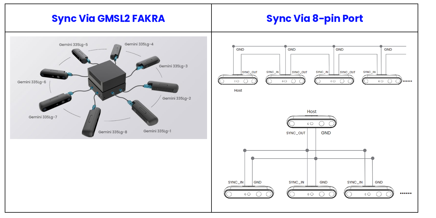
The platform currently supports two synchronization methods.

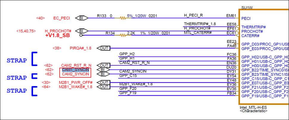
TGPIO connection diagram


Solution Implementation

BIOS Configuration

The following BIOS features must be enabled before using the synchronization framework:

  • Enable TGPIO support
  • Integrate BIOS support for:
    • INTC1023
    • INTC1024

PTP device verification


TGPIO Hardware Routing

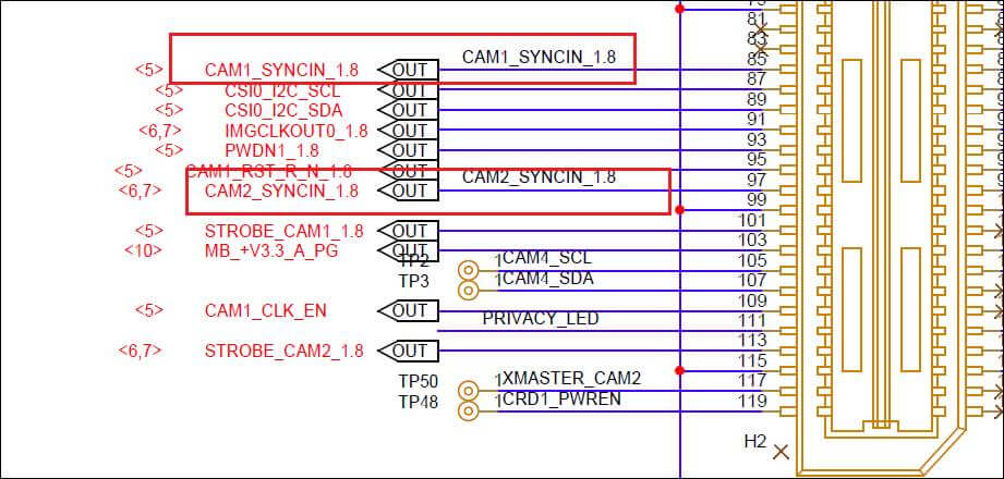
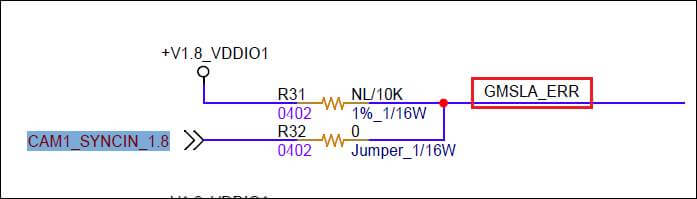
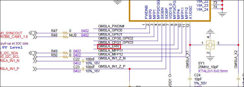
Verify that the CPU TGPIO signal is correctly connected to the GMSL deserializer.

The following example uses the ASR-A502 platform.

CPU to 120-pin Connector

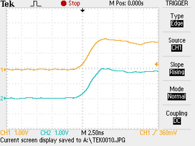
Time comparison output PPS signal waveform

120-pin Connector to MAX9296A (GMSL Daughter Board)

Continuous synchronization flow Continuous synchronization flow Continuous synchronization flow


Verify the PTP Device and Build the Test Utility

Identify which /dev/ptpX node corresponds to the TGPIO device.

The expected result should be similar to the example below, where the TGPIO device is mapped to /dev/ptp3.

udevadm info /dev/ptp* | grep virtual

Continuous synchronization flow

Build the testptp utility according to the kernel version in use.

Reference source:

https://github.com/intel/linux-intel-lts/tree/lts-v6.12.36-linux-250711T071314Z

Build procedure:

cd <kernel source folder>

make headers_install ARCH=x86_64
make -C tools/testing/selftests/ TARGETS=ptp

Navigate to the generated binary location:

cd tools/testing/selftests/ptp

The folder contains:

  • testptp executable
  • testptp.c source code

The source code also demonstrates how to control TGPIO through IOCTL interfaces.


Time Offset Measurement

Compare the TGPIO PTP hardware clock with Linux CLOCK_REALTIME to calculate the synchronization offset.

sudo ./testptp -d /dev/ptp3 -X

Continuous synchronization flow


PPS Signal Generation

For hardware validation, testptp can generate a PPS waveform through TGPIO output pins.

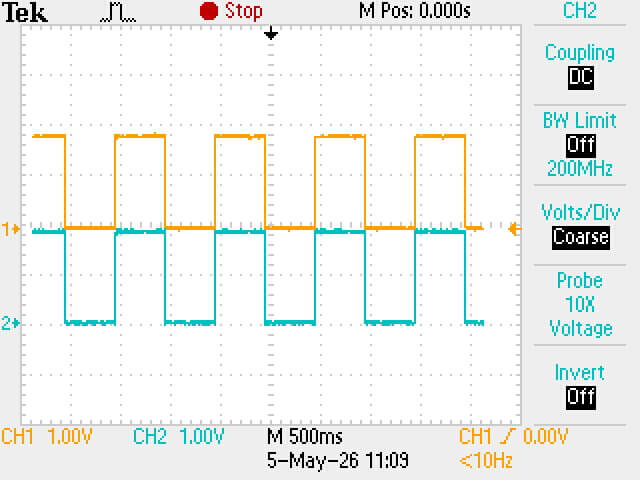
The PPS signal should be verified using an oscilloscope.

The ASR-A502 GMSL daughter board includes two deserializer ICs.

TIME_SYNC_0 → PPS Output

Example using /dev/ptp3:

sudo ./testptp -d /dev/ptp3 -i 0 -L 0,2 -p 1000000000
  • 1000000000 represents a 1-second cycle period
  • Output waveform:
    • 50% high level
    • 50% low level
  • The generated PPS signal is not phase-aligned with Linux system time

TIME_SYNC_1 → PPS Output

sudo ./testptp -d /dev/ptp3 -i 1 -L 1,2 -p 1000000000
Continuous synchronization flow Continuous synchronization flow


Continuous Synchronization Service

Over long operating durations, drift between Linux system time and the TGPIO PTP hardware clock may gradually increase.

For robotics and AMR applications requiring stable long-term synchronization, a continuous calibration mechanism is strongly recommended.

Intel provides a reference implementation:

RDC#785823
Precision Time Measurement Test Scripts and Timed-GPIO for Linux*
https://cdrdv2.intel.com/v1/dl/getContent/785823?explicitVersion=true

The package includes a sample utility, pps, which continuously aligns the PPS signal with Linux system time while controlling TGPIO output.

Source location:

785823_PTM_Test_Scripts_TGPIO_for_Linux_Rev_1_0/
└── Time-Aware-GPIO-Support/
└── user-code/
└── tgpio_pps/
└── pps.c

Before compiling pps.c, retrieve the TSC/clock ratio and nominal core crystal clock frequency using the following command:

cpuid -1 | grep -E "(Time Stamp|TSC/clock|nominal)"

Continuous synchronization flow

Modify the required definitions inside pps.c, then rebuild the utility.

Continuous synchronization flow Continuous synchronization flow

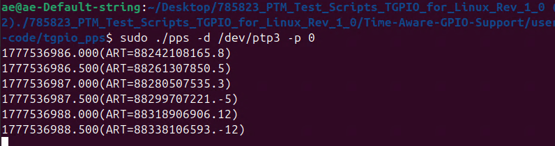
For TIME_SYNC_0 PPS output:

sudo ./pps -d /dev/ptp1 -p 0

This service continuously aligns the generated PPS signal with Linux system time.

Continuous synchronization flow


Notes

  • The /dev/ptpX index may vary across different hardware platforms and BIOS versions.
  • PPS timing accuracy should always be validated using an oscilloscope.
  • Continuous synchronization services are strongly recommended for long-duration robotics and autonomous system deployments.
  • Accurate hardware time synchronization is essential for reliable SLAM, sensor fusion, and AI perception workloads in multi-camera systems.