Simulation & SDG Generation
The principal cost of physical recording is labour: a single demonstration requires several tens of seconds, while the number of episodes needed to achieve stable training results may reach several dozen, with workpiece repositioning and the re-recording of deficient episodes required throughout.
The simulation environment offers an alternative addressing this cost structure: following a single demonstration by the operator, the platform automatically generates a full batch of varied training data.
Positioning The simulation environment is not a replacement for physical recording. Both routes produce datasets of the same format and feed the same training line, and in practice most deployments adopt both.
1. Hardware requirements
| Hardware | Required |
|---|---|
| Camera | No; imagery is rendered by the simulation environment |
| Leader Arm (operator side) | Yes |
| Follower Arm (execution side) | No; this side is virtual |
The simulation environment dispenses with the Follower Arm and with physical cameras. The demonstration motion must still be performed by the operator using a physical Leader Arm; the simulation environment substitutes both the execution side and the image source with virtual equivalents.
All imagery in simulation data is rendered by the simulation environment, in a fixed two-camera configuration — Wrist Camera and Top Camera — consistent with the configuration recommended for physical recording. This is preconfigured and requires no manual placement or naming; whether a physical camera is connected has no bearing on the content of simulation data, and the hardware readiness check on the simulation page does not check for cameras.
The environment must be built before first use The simulation environment is not deployed as part of the installation flow. Before first use, the source must be obtained and the container images built; see Optional: building the simulation environment.
2. Virtual-physical alignment: offset calculation
The first operation on entering the simulation environment is to align the virtual Follower with the physical Leader.
Rationale
The arm moved by the operator is the physical Leader Arm, while the arm moving synchronously on screen is virtual. Their physical bases differ: the physical arm carries assembly tolerances and variation in mounting reference, whereas the virtual arm is ideal geometry constructed from a model file. Consequently, even where both are in a correct state, the joint angle readings corresponding to the same pose will not be identical; this difference constitutes the offset.
Distinction from arm calibration The purpose of arm calibration is to align the physical arm's readings with physical reality, and it constitutes a basic hardware configuration task. The purpose of offset calculation is to align the virtual Follower with the physical Leader, and it applies only when the simulation environment is used.
Procedure
The function is located in the "Offset Calculation" tab of the Simulation Environment Settings, and comprises three steps: preparation pose, offset calculation, and offset confirmation.
Step 1: Zero position. Move the Leader arm to the zero position and hold it stationary for the following 10 seconds. The on-screen prompt reads "Once both arms are in position and stationary, press Next, or remain stationary for 3 seconds to begin".
Step 2: Offset calculation. Over a period of 10 seconds the system continuously reads the joint angle differences between the two arms and takes the mean value as the offset, displaying the sample count and remaining seconds in real time. As a mean value is taken, the arm must remain stationary throughout sampling; if the arm is still supported by hand or is descending under gravity, the readings will drift continuously and the resulting mean will not correspond to any actual pose.
Step 3: Offset confirmation. The screen lists the calculated results for the five joints joint1 to joint5, each row containing a "calculated (avg)" and an "adjusted offset" column, the latter an editable field prefilled with the calculated value. On confirmation, select "Apply Offset to Config". Where recalculation is required, "Re-record" may be selected; "Reset" reverts manual adjustments to the calculated values.
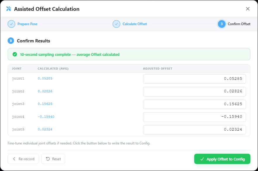
Under normal circumstances the "adjusted offset" requires no modification and the calculated value may be used as it stands. The field is editable in order to address residual deviation still evident at visual verification, and constitutes an exception rather than a routine step.
Verification
Following the write to the configuration file, move the physical Leader and observe the virtual arm on screen; the poses of the two should correspond. If the virtual arm consistently deviates by a fixed angle, this step has not been correctly completed and must be repeated. This visual confirmation determines the correctness of all subsequent simulation data.
3. Simulation environment settings
Aside from offset calculation, the environment settings tabs comprise the following four items:
| Tab | Configured content |
|---|---|
| Cube | Randomization range for the target object's position (x / y / z / z-rotation) |
| Box | Randomization range for the container's position and orientation (x / y / z / three-axis rotation) |
| Top camera | Camera position and rotation, together with a randomization range per axis |
| Robot arm | Per-joint offsets; the fields vary by model |
Randomization range
The randomization range is the core setting of SDG and also the item most susceptible to misconfiguration.
Its function is as follows: on each data generation cycle, the platform selects the object's placement position at random within the specified range. Where the range is set to ±5 cm, one hundred generated episodes will cover one hundred arrangements of the object distributed across a 10 cm square area.
| Setting | Result |
|---|---|
| Range too narrow (approaching zero) | The generated episodes are nearly identical, equivalent to repeated duplication of a single episode; only one situation is substantively covered |
| Range appropriate | The variation encountered in actual operation is covered, and the model learns to adjust its motion according to object position |
| Range too wide | Objects are placed where the arm cannot reach or the camera cannot cover, generating a substantial volume of failed samples; the success rate declines markedly |
The configuration principle is to base the range on the degree of variation present in actual operation. The range may be set somewhat generously, but must not exceed the arm's working envelope. The recommended method is to measure the maximum probable displacement of the workpiece in actual operation and to use that distance as the basis for configuration.
Randomization range of the top camera
In addition to position and rotation, the camera tab also provides a randomization range. The purpose of this setting differs from that of the object: it enables the model to identify the object where minor differences in camera angle exist. For scenarios requiring subsequent deployment to multiple hosts, this setting carries substantive value, as camera mounting positions cannot be entirely identical across stations.
This setting should, however, be more conservative than that of the object. An excessive camera randomization range produces invalid data in which the object lies outside the frame.
4. Virtual recording
Once the environment is configured, the recording procedure is comparable to physical recording, with the control bar likewise providing Start, Retry, Next episode, and Finish. The demonstration quality criteria apply in full.
The difference lies in the procedure following recording. Physical recording writes the dataset upon selection of "Finish", whereas simulation recording presents four options:
| Option | Purpose |
|---|---|
| Replay recording | Replays the demonstration for quality confirmation |
| Mimic generation | Proceeds to the generation stage, producing a full batch from this demonstration |
| Export dataset | Exports only this demonstration as a dataset, without generation |
| Record again | Repeats the demonstration |
Replay and confirm before generation The cost structures of the two routes differ. In physical recording, the impact of a single deficient episode is limited to that episode; in simulation generation, the demonstration serves as the master copy for the entire subsequent batch, and any hesitation, correction, or path deviation within it is reproduced in full across every generated episode.
The demonstration should therefore be replayed and its quality confirmed before proceeding to the generation stage.
Where a previous session was left incomplete, on next entering the simulation environment the platform reports "Previous Session Found", names the recording concerned, and asks whether to continue from the point of interruption:
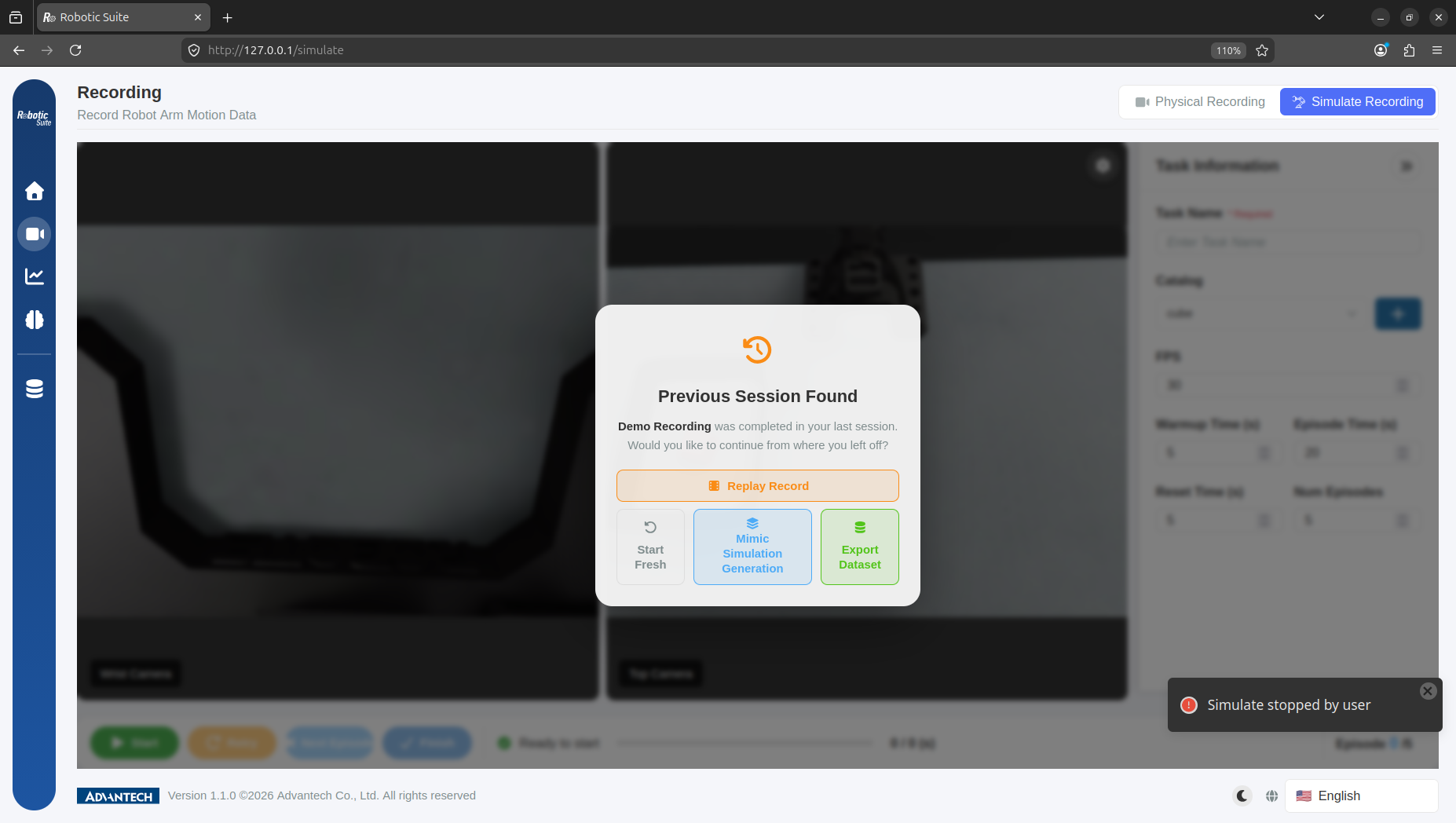
The options offered here are the same as those following recording — Replay Record, Mimic Simulation Generation, and Export Dataset — with the addition of "Start Fresh". An interrupted session therefore requires no re-recording of the demonstration and may proceed directly to generation; selecting "Start Fresh", however, discards the previous demonstration.
5. Training data generation
Selecting "Mimic generation" opens the "Training Data Generation" configuration screen, on which two parameters must be set:
Number of episodes to generate (range 1–500): the number of training episodes to be generated, which directly determines the training data volume.
Number of parallel devices (range 1–16): the number of simulation instances executed concurrently. This parameter does not affect data content and influences only generation speed. The value should be determined by the host's compute resources; if it exceeds the host's capacity, the instances will compete for resources and the total duration will increase. A mid-range starting value is recommended, with adjustment following observation of the generation rate.
Monitoring indicators during generation
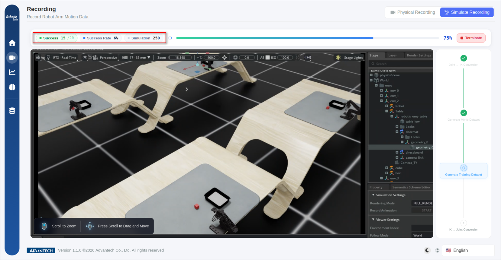
Once started, a progress bar is displayed at the top of the screen comprising four indicators:
| Indicator | Meaning |
|---|---|
| Success | Episodes successfully generated against the target count |
| Success rate | Successes as a percentage of simulation attempts |
| Simulation | Cumulative simulation attempts |
| PROGRESS | Completion percentage |
The success rate constitutes the principal basis for assessment. Following each simulation the platform verifies whether the motion actually completed the task, and those that did not are excluded from the dataset. A low success rate therefore does not indicate an execution error, but reflects the appropriateness of the environment configuration:
| Success rate | Probable cause | Remedy |
|---|---|---|
| Markedly low | Randomization range configured too wide; some object positions lie outside the arm's reach | Reduce the cube and box randomization ranges |
| Near zero | Virtual-physical alignment not correctly completed, or the demonstration itself did not complete the task | Repeat the offset calculation and replay the demonstration for confirmation |
| Near maximum but generation is slow | The range may be configured too narrow | Widening may be considered in order to obtain greater variation |
The figure above illustrates the first case: 250 simulation attempts have yielded only 15 successful episodes, a success rate of 6%. The run should be terminated and the randomization range reviewed rather than allowed to complete — at better than ten attempts per successful episode, the time cost of the batch is several times what it would be under a sound configuration.
Where an anomalous success rate is observed, it is recommended to select "Terminate", correct the configuration, and re-execute, rather than allowing the batch to run to completion.
The four stages of the generation process
The Pipeline rail on the right of the screen indicates the stage currently in execution as a vertical sequence, with completed stages marked by a green check and the stage in progress highlighted (the third stage, "Generate Training Dataset", in the figure above):
Joint → IK conversion → Mimic annotation dataset → Training dataset → IK → Joint conversion
The technical detail of each stage need not be understood, but awareness that the process comprises four stages assists in interpreting progress: the progress bar exhibits a brief pause during stage transitions, which is expected behaviour.
6. Export and integration into the training line
On completion of generation, the platform provides three options: play training data, export dataset, and regenerate training data. It is recommended that several generated episodes be sampled for review before export.
On export, the platform performs an HDF5 → LeRobot format conversion. Following conversion, the data is identical in format to the output of physical recording, may be selected directly on the training page, and may be merged with physical datasets into a single dataset in the data tools.
7. The Sim-to-Real gap
The simulation environment cannot fully reproduce the physical conditions of the real world. This divergence, termed the Sim-to-Real Gap, constitutes the intrinsic limitation of simulation data.
Conditions that the simulation environment generally cannot reproduce include: actual lighting variation and reflection, surface friction and slippage characteristics, minor deformation during gripper actuation, and the mechanical backlash and vibration of a physical arm. Models trained solely on simulation data therefore generally exhibit reduced performance in real environments.
Two methods of compensation are used in practice:
First, the use of mixed datasets. Simulation data constitutes the bulk of the data volume, with several physical demonstrations merged in so that the model covers the characteristics of the real environment. This is the lowest-cost and most direct method.
Second, incorporating variation into the randomization ranges. The randomization of lighting, camera angle, and object position exists precisely to reduce the model's dependence on any single condition.
Irrespective of the method adopted, an inference verification must be completed on physical hardware prior to going live.
Next: Dataset management.