Arm Calibration
Applicable scope This chapter applies to SO-101. The "Arm Calibration" button is displayed only when the model is set to SO-101.
The necessity of calibration
A servo reports its internal raw scale value rather than the actual angle of the joint. The system must first obtain the actual range of motion of that motor on that particular arm before the scale can be converted into a physically meaningful angle.
This range cannot be derived from a specification sheet, as it depends on physical assembly conditions: screw positions, linkage lengths, and cable routing. Differences exist even between two arms from the same production batch. This constitutes an inherent divergence between hardware and specification, and is the reason calibration cannot be automated.
Entry point and role selection
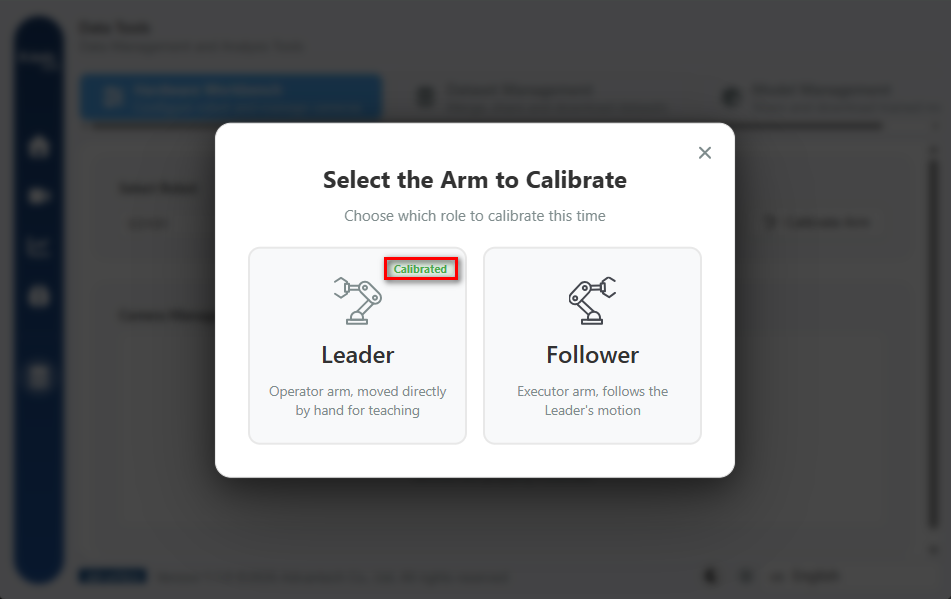
The calibration function is located at Data Tools → Hardware Settings → Arm Calibration. On entry, the role to be calibrated (Leader or Follower) must be selected; roles already calibrated are marked with a "Calibrated" badge (outlined in red above; in this example the Leader is complete and the Follower has not yet been performed).
This state is restored from the backend calibration record rather than from browser-side storage, and is therefore displayed correctly when the interface is opened on a different computer.
Calibration procedure
The wizard provides guidance through a four-step progress bar, with a 3D arm model and live connection status displayed on the right of the screen.
Step 1: Preparation pose
Move the arm to a safe preparation pose and confirm that each joint moves freely. Subsequent steps require every motor to be rotated to its physical limit, so the range of motion must first be cleared to avoid collision with workpieces or fixtures.
Step 2: Move to the middle position
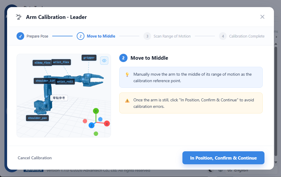
Move the arm manually to the middle of its range of motion to serve as the calibration reference point, then click "In Position, Confirm & Continue".
The 3D model on the left of the screen labels the six joint names together with the zero reference, and may be used to identify the position of each joint on the physical arm.
The system samples at the instant the button is pressed. If the arm is still supported by hand, or is descending under gravity, the value obtained will be a drifting one. Sampling should be performed only after the arm has come fully to rest.
Step 3: Scan the range of motion
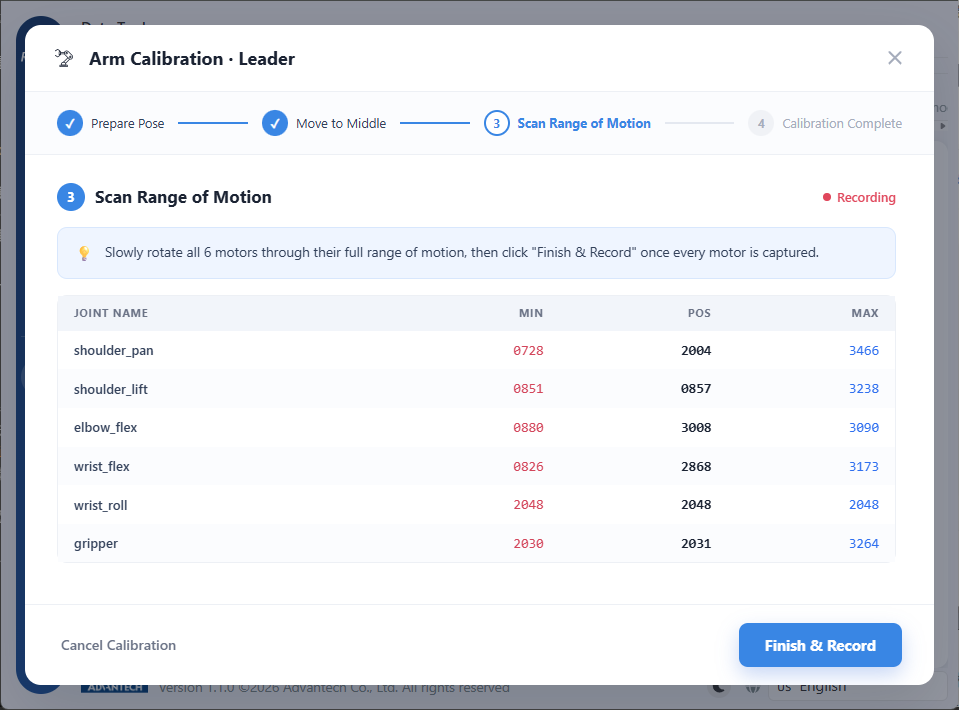
This step constitutes the core of calibration. Following the on-screen prompt, rotate all six motors slowly to both ends of their range of motion, while the system displays the minimum (MIN), current (POS), and maximum (MAX) values for each motor in a live table, with a "Recording" indicator in the upper right. Once all six motors have been scanned, click "Finish & Record".
That table is the sole acceptance criterion for this step. If a joint's minimum and maximum values are approximately equal, the motor in question was not actually rotated and the scan must be repeated for it. The figure above illustrates this: all three values in the wrist_roll row read 2048, indicating that the joint has not been rotated since this step was entered. Clicking "Finish & Record" in this state would record a range of motion of zero for that joint.
The six SO-101 joints are as follows:
| Joint | Description |
|---|---|
shoulder_pan | Shoulder horizontal rotation |
shoulder_lift | Shoulder pitch |
elbow_flex | Elbow flexion |
wrist_flex | Wrist pitch |
wrist_roll | Wrist roll |
gripper | Gripper open/close |
It is recommended to proceed in order from the shoulder to the gripper, concentrating on one joint at a time.
Common operational errors and their consequences:
| Operation | Consequence |
|---|---|
| Excessive rotation speed | Sampling has an upper frequency limit; endpoints may be skipped and a smaller-than-actual range recorded |
| Rotation only to the midpoint | The recorded range is too small, and the arm cannot reach certain poses during demonstration |
| Gripper not scanned | Grasping cannot be learned. gripper is also a motor, and is the most commonly omitted item |
| Collision with an obstacle during the scan | A false endpoint constrained by external force is recorded, with possible damage to the servo |
"Slowly" and "to both ends" are specific requirements: rotation should continue until resistance is felt and the mechanism reaches the end of its travel.
Step 4: Completion
The system writes the calibration data and displays the final measured range for each joint. The table should be reviewed again at this point to confirm that all six joints have a plausible interval.
A "Calibrate Follower" button is then provided to guide completion of the second arm. The work of this chapter is complete only when both arms display the "Calibrated" badge.
Cancellation during the procedure
If the wizard is closed or "Cancel Calibration" is selected during the procedure, the system reports "Calibration cancelled or aborted; no calibration data was written". An interruption does not produce an incomplete configuration, and the procedure may be repeated.
Distinction from "Offset Calculation"
The platform provides a further function named "Offset Calculation", located within the Simulation Environment Settings tabs. It is a distinct operation from the arm calibration described in this chapter:
| Function | Purpose |
|---|---|
| Arm calibration (this chapter) | Aligns the physical arm's readings with physical reality |
| Offset calculation | Aligns the virtual Follower with the physical Leader |
"Offset Calculation" need not be performed when using the physical hardware workflow. It is applicable only when the simulation environment is used; see Simulation & SDG Generation.
Next: Policy selection.