URDF Robot Model
URDF (Unified Robot Description Format) is the XML format ROS 2 uses to describe a robot's physical structure — its links, joints, and geometry — so that tools like RViz2, TF2, and motion-planning frameworks can reason about it consistently.
Overview
A robot model defines physical structure and geometry. In ROS 2, this is described primarily with URDF, together with 3D mesh files (STL or DAE are common) for visual and collision geometry. While a mesh describes what a part looks like, URDF defines how parts are connected, how they move, and their physical properties.
Why It Matters
URDF is the shared description that makes visualization (RViz2), coordinate frames (TF2), and motion planning (see Manipulation's Motion Planning) all consistent with each other. Get the URDF wrong — a missing joint limit, a swapped axis, an incorrect parent/child link — and every tool built on top of it inherits the same mistake.
Core Concepts
What URDF Describes
- Links: rigid bodies (visual mesh, collision geometry, inertial properties).
- Joints: how one link moves relative to another (
revolute,prismatic,continuous,fixed, and others), including motion limits. - Transforms: the fixed geometric offsets defined by joint origins, together with joint motion, determine the relationship between parent and child links. TF2 and
robot_state_publisheruse this information to compute the robot's live coordinate frames — see TF2.
Basic Structure
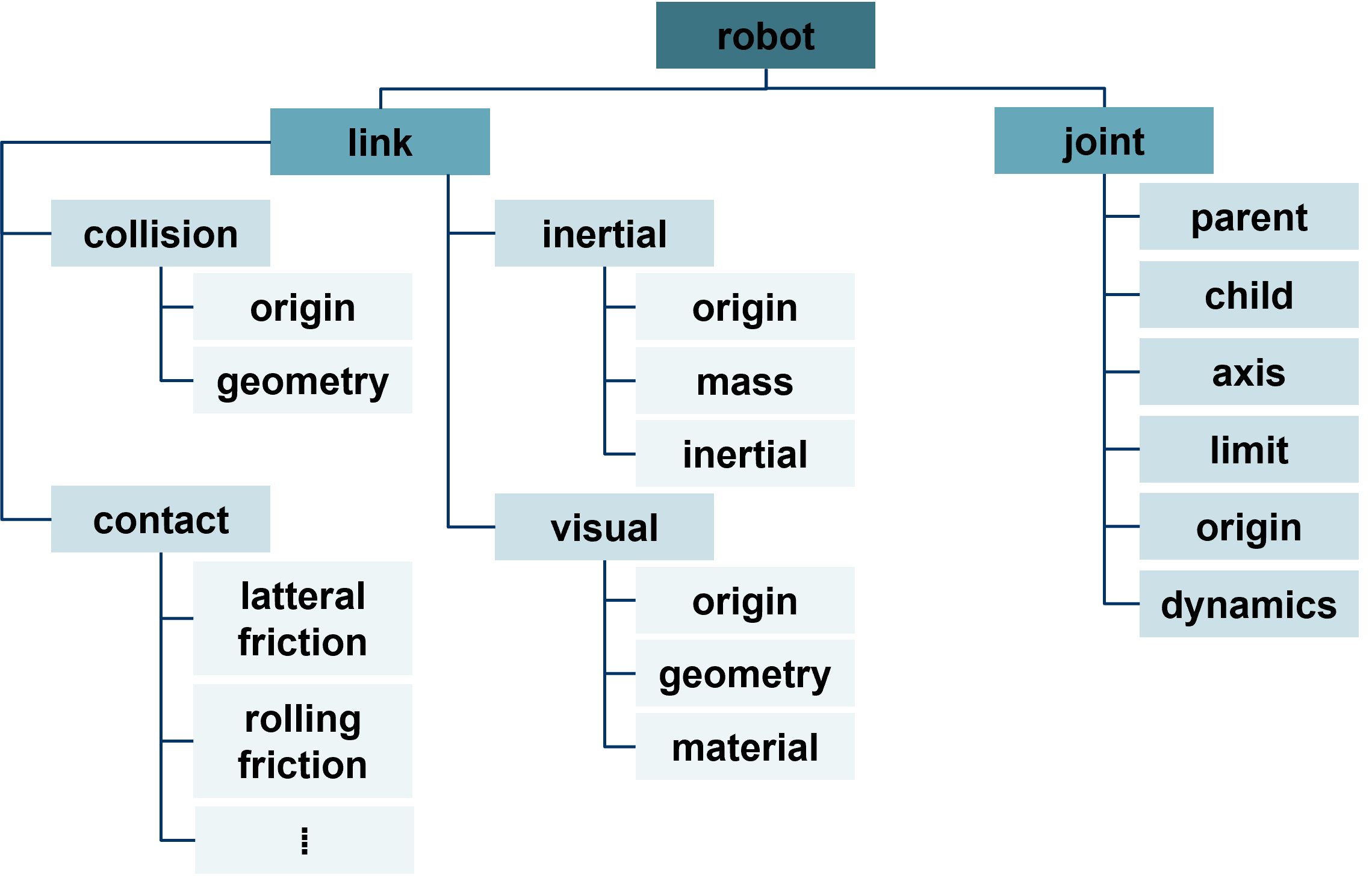
<robot name="robot_name">
  <!-- Link definitions -->
  <link name="link_name">
    <visual>...</visual>
    <collision>...</collision>
    <inertial>...</inertial>
  </link>

  <!-- Joint definitions -->
  <joint name="joint_name" type="revolute">
    <parent link="link1"/>
    <child link="link2"/>
    <axis xyz="0 0 1"/>
    <limit lower="-3.14" upper="3.14" effort="100" velocity="1.0"/>
  </joint>
</robot>
From URDF to a Live TF Tree
A URDF file only describes the robot's kinematic structure — it does not, by itself, publish any transforms. At runtime, robot_state_publisher combines the URDF with live /joint_states messages to compute and publish the actual link transforms on /tf and /tf_static. See TF2 for how this works and what can go wrong.
URDF and ros2_control
URDF can optionally include a <ros2_control> tag describing which joints are controllable and what hardware interface backs them. This is common for physical manipulators and mobile bases, but not mandatory — a purely visual or simulation-only robot model can omit it entirely. See the Manipulation section's Arm Action page for how ros2_control fits into a full manipulator control stack.
Hands-on Steps: Visualizing a URDF in RViz2
1. Publish the Robot Description
Launch robot_state_publisher with the robot description loaded into its robot_description parameter. Depending on the ROS 2 distribution and tooling, the description may also be made available through a robot_description topic for consumers such as RViz2.
2. Open RViz2 and Add a Display
In RViz2 (RViz2):
- Click Add in the lower-left panel.
- Select RobotModel from the display types list.
3. Configure the RobotModel Display
- Set Description Source to match how your robot description is provided, such as a topic or file when supported by your RViz2 version.
- Confirm that the selected source contains a valid robot description. An unavailable or invalid description is a common reason the model does not appear.
4. Troubleshooting the Display
If the model does not appear, try toggling Visual Enabled off and back on, and confirm the RViz2 Fixed Frame exists in the current TF tree (see TF2).
5. Managing Links
Under the Links section of the RobotModel display, toggle visibility of individual links for a focused view of specific parts.
Coordinate Systems and Transforms
Before adjusting URDF joint parameters, make sure you understand frames and the right-hand rule described in TF2, since joint axes and transform offsets in URDF follow the same convention.
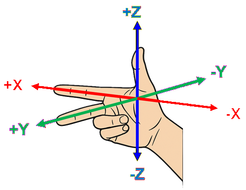
Thumb    → X-axis (positive)
Index    → Y-axis (positive)
Middle   → Z-axis (positive)
The direction each finger points represents the positive axis; the opposite direction is the negative axis.
This convention determines the positive direction of a joint axis. Joint limits are then expressed relative to that joint-coordinate convention.
Expected Result
RViz2's RobotModel display shows the robot's links in their correct relative positions, and the model updates live as /joint_states changes, without needing to restart RViz2 or the description publisher.
Useful Commands
ros2 param get /robot_state_publisher robot_description | head -c 200   # confirm it is set (long output)
ros2 topic echo /joint_states
ros2 run tf2_tools view_frames                                          # confirm every link has a TF parent
Common Problems
- RobotModel display stays empty — the description was never published, or Description Source does not match how it is actually provided; check with
ros2 topic list | grep robot_descriptionor the equivalent parameter. - Model appears but does not move —
/joint_statesis not being published, or joint names in the URDF do not match the names used by the publisher of/joint_states. - Some links are missing or disconnected — run
ros2 run tf2_tools view_frames(see TF2) to confirm every link has a continuous parent chain back to the root frame. - Motion looks mirrored or rotated incorrectly — double-check joint
axissigns against the right-hand rule above; a flipped axis is a common URDF authoring mistake.
Key Takeaways
- URDF describes structure (links, joints, limits, inertial and visual properties) — it does not by itself publish live transforms.
robot_state_publishercombines URDF with/joint_statesto produce the live TF tree used by RViz2, MoveIt, and other tools.ros2_controlintegration is common for physical robots but optional, not mandatory, in every URDF.- URDF is essential for visualization, simulation, kinematics/dynamics, and motion planning — get the axis conventions and joint limits right early.
Next
Continue to TF2 if you have not already, or to Gazebo to simulate the same robot model physically.