RViz2
RViz2 is the standard 3D visualization tool in ROS 2. It can visualize sensor data, coordinate frames, robot models, maps, paths, and other ROS 2 messages in a shared 3D scene.
Overview
RViz2 helps you inspect what a robot system is publishing and how that data is positioned in space. It is commonly used for development, debugging, simulation, and monitoring.
Common display types include:
- TF — coordinate frames and their relationships
- RobotModel — robot links and joints described by URDF
- PointCloud2 — depth-camera or LiDAR point clouds
- LaserScan — 2D laser scan data
- Image — camera images
- Map — occupancy grids
- Path — planned or recorded trajectories
RViz2 is a visualization tool only. It does not generate sensor data, robot state, or transforms by itself; those must be published by other ROS 2 nodes.
Why It Matters
Many ROS 2 problems are easier to understand visually than from terminal output alone. RViz2 can quickly reveal missing transforms, incorrectly positioned sensor data, unexpected robot poses, or planning results that do not match the physical robot.
It is especially useful together with TF2, URDF Robot Model, and the Mobility and Manipulation examples in Robotic Suite.
Core Concepts
Fixed Frame
RViz2 visualizes all data relative to a selected Fixed Frame.
Typical choices include:
mapodombase_link
The appropriate frame depends on the application.
The selected Fixed Frame must exist in the current TF tree. If RViz2 cannot transform incoming data into the Fixed Frame, the corresponding display will report an error and may not render.
You can inspect the TF tree with:
ros2 run tf2_tools view_frames
or inspect a specific transform with:
ros2 run tf2_ros tf2_echo <source_frame> <target_frame>
See TF2 for more details.
Displays
RViz2 uses Displays to visualize different kinds of ROS 2 data.
Each display subscribes to a topic, uses TF information, or reads another configured data source depending on the display type.
Examples:
- Add TF to inspect coordinate frames.
- Add RobotModel to visualize a URDF-based robot.
- Add PointCloud2 to visualize point-cloud data.
- Add LaserScan to visualize a 2D LiDAR scan.
- Add Image to inspect a camera topic.
Each display has its own properties, such as topic name, queue size, style, and frame-related settings.
Hands-on Steps
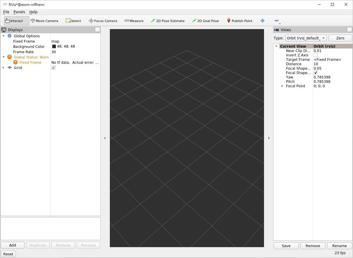
1. Start RViz2
ros2 run rviz2 rviz2
2. Select the Fixed Frame
In the Displays panel:
- Expand Global Options.
- Set Fixed Frame to a frame that exists in your TF tree, such as
base_link,odom, ormap.
If you are unsure which frames are available, run:
ros2 run tf2_tools view_frames
3. Add a Display
Click Add in the Displays panel and select the display type you need.
For example, to inspect the TF tree:
- Click Add.
- Select TF.
- Confirm that the frame axes and names appear in the 3D view.
To inspect a camera or sensor topic, add the corresponding Image, LaserScan, or PointCloud2 display and select the appropriate topic.
4. Visualize a Robot Model
To visualize a robot described by URDF:
- Add a RobotModel display.
- Set Description Source to match how your robot description is provided.
- Confirm that the required TF frames are available.
See URDF Robot Model for the full robot-description setup.
Expected Result
RViz2 opens successfully and displays the data selected in the Displays panel.
For TF-based data:
- The configured Fixed Frame exists.
- TF-connected displays render without transform errors.
- Robot models and sensor data appear in the expected positions.
For topic-based displays:
- The selected topic exists.
- The topic message type is supported by the chosen display.
- Incoming data updates while the publisher is running.
Useful Commands
# Start RViz2
ros2 run rviz2 rviz2

# Inspect available topics
ros2 topic list

# Inspect one topic and its publishers/subscribers
ros2 topic info <topic_name> -v

# Inspect TF
ros2 run tf2_tools view_frames
ros2 run tf2_ros tf2_echo <source_frame> <target_frame>
Common Problems
- Nothing appears in the 3D view — confirm that the selected Fixed Frame exists and that the display is configured with the correct topic or data source.
- A display reports a TF error — RViz2 cannot transform the incoming data into the Fixed Frame. Check the TF tree with
tf2_echoorview_frames. - RobotModel does not appear — verify the robot description source, URDF, and TF tree. See URDF Robot Model.
- Sensor data appears in the wrong position — check the message
frame_idand the corresponding transform to the Fixed Frame. - A topic is available but nothing is displayed — confirm that the topic type matches the selected RViz2 display and check for QoS or TF issues. See Troubleshooting.
Key Takeaways
- RViz2 visualizes ROS 2 data but does not generate that data itself.
- Every 3D display is interpreted relative to the configured Fixed Frame.
- TF must connect the incoming data frame to the Fixed Frame for spatial data to render correctly.
- Displays such as TF, RobotModel, PointCloud2, LaserScan, and Image provide different views into a running ROS 2 system.
- RViz2 is most effective when used together with CLI inspection tools and TF diagnostics.
Next
Continue to rqt_graph to visualize the ROS 2 node/topic graph, or revisit TF2 and URDF Robot Model when debugging spatial or robot-model issues.