Workflow Overview
The platform home page presents a clickable flow diagram that serves as the navigation reference for the overall functionality. This chapter explains the architecture represented by that diagram, and may be read alongside the walkthrough video.
Two data routes and a single training line
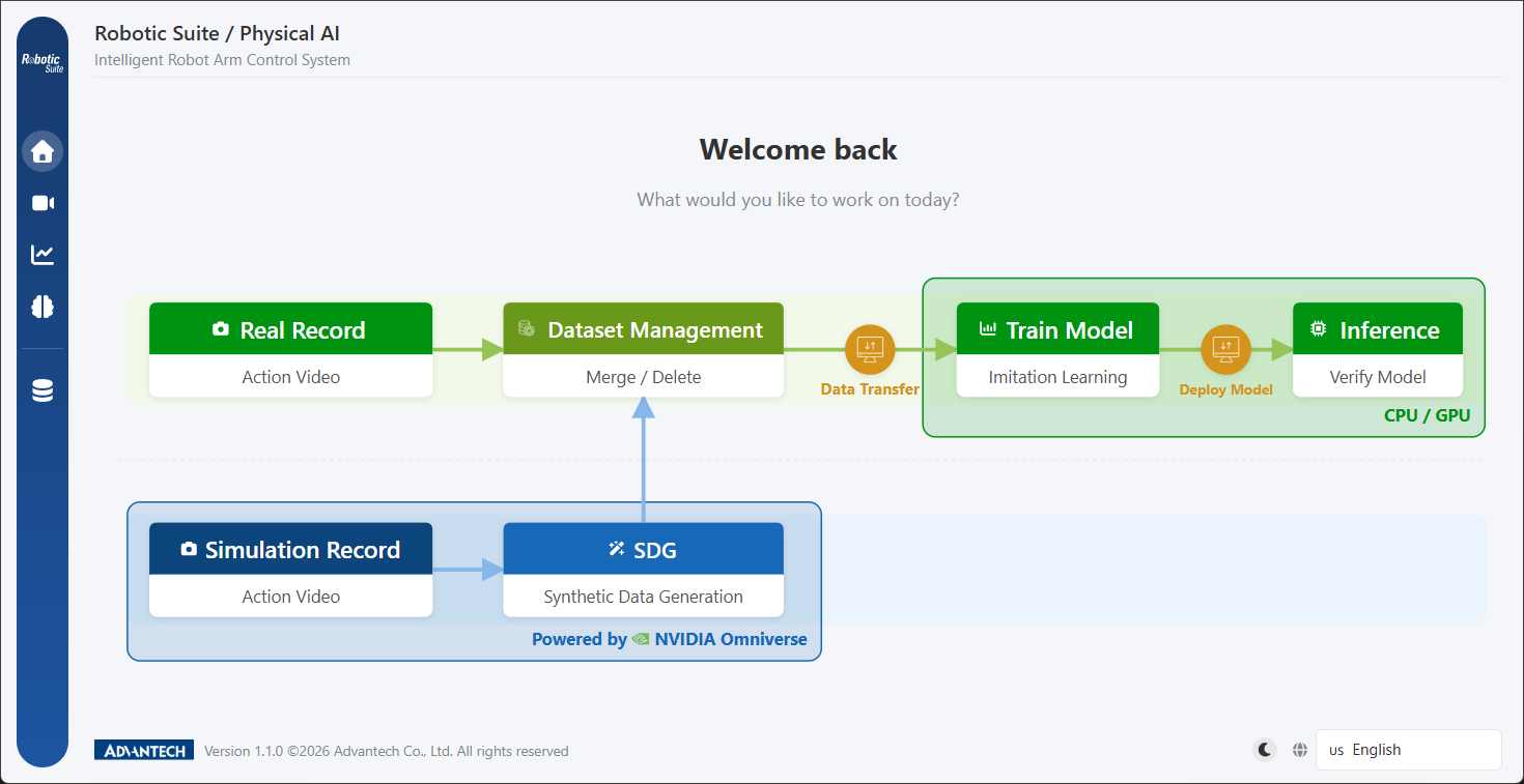
- Physical route (green, upper): the operator guides the Leader Arm through the demonstration, recording one episode at a time.
- Simulation route (blue, lower): following a single demonstration, SDG automatically generates a full batch of varied data.
The two routes are not mutually exclusive. Both produce datasets in the LeRobot standard format and feed the same training line. In practice, most deployments use both: the simulation route to establish data volume, and physical data to supply the physical detail that simulation cannot reproduce.
The diagram also marks two cross-lane paths, dataset transfer and model deployment. Both refer to moving assets between hosts using short codes: datasets are transferred to the training host, and models to the production host.
The five interface entry points
The sidebar is ordered according to the workflow:
| Entry point | Function | Corresponding chapter |
|---|---|---|
| Home | The flow diagram; nodes may be clicked to navigate to the corresponding function | This chapter |
| Record | Prompts for a choice between physical and virtual recording on entry | Demonstration Recording |
| Training | Dataset and policy selection, parameter configuration, and training status monitoring | Model Training |
| Inference | Inference verification and model conversion | Inference & Model Conversion |
| Data Tools | Hardware settings, dataset management, and model management | Hardware Integration & Calibration, Data Tools |
It should be noted that hardware settings are located within Data Tools. Robot model selection, camera management, and arm calibration are all consolidated under the "Data Tools → Hardware Settings" tab, which is the function area least readily located on first use.
The complete workflow
- Hardware connection: connect the robotic arms and cameras, and confirm the correct model on the hardware settings page (Hardware Integration & Calibration).
- Calibration: SO-101 requires serial port detection and six-axis range calibration.
- Policy determination: select ACT or GR00T N1.5. This decision simultaneously establishes the deployment hardware (Policy Selection).
- Demonstration recording: by physical recording or simulation-based SDG generation (Demonstration Recording).
- Data review: preview episode by episode in Data Tools and remove those of insufficient quality.
- Training: select the dataset, policy, and compute device, configure the parameters, and start (Model Training).
- Training monitoring: observe loss and GPU utilization, and terminate early in the event of anomalies.
- Inference verification: execute inference and evaluate the arm's performance (Inference & Model Conversion).
- Conversion and deployment: perform model conversion for the target hardware and transfer to the production host using a short code (Data Tools).
The hardware readiness check
The platform performs a hardware readiness check before entry to the Record, Simulate, and Inference pages, and issues a notification when components are missing. The items checked vary by page:
| Page | Camera | Leader Arm | Follower Arm |
|---|---|---|---|
| Record | Required | Required | Required |
| Simulate | Not checked (imagery is rendered by the simulator) | Required | Not checked (the Follower is virtual) |
| Inference | Required | Not checked (the model assumes the operator's role) | Required |
This table also describes the operating logic of the platform. See the hardware readiness check.