Inference & Model Conversion
The inference page constitutes the verification stage of the overall workflow: the model assumes the role of the operator, and the robotic arm executes the task autonomously. The decisions made in the preceding chapters — hardware calibration, camera viewpoint, demonstration quality, policy selection, and training parameters — all present their cumulative result at this stage.
Pre-deployment model conversion is likewise performed on this page. The conversion section expands in place within the inference settings drawer, requiring no page change, a design reflecting the fact that conversion and verification constitute a continuous operation in practice.
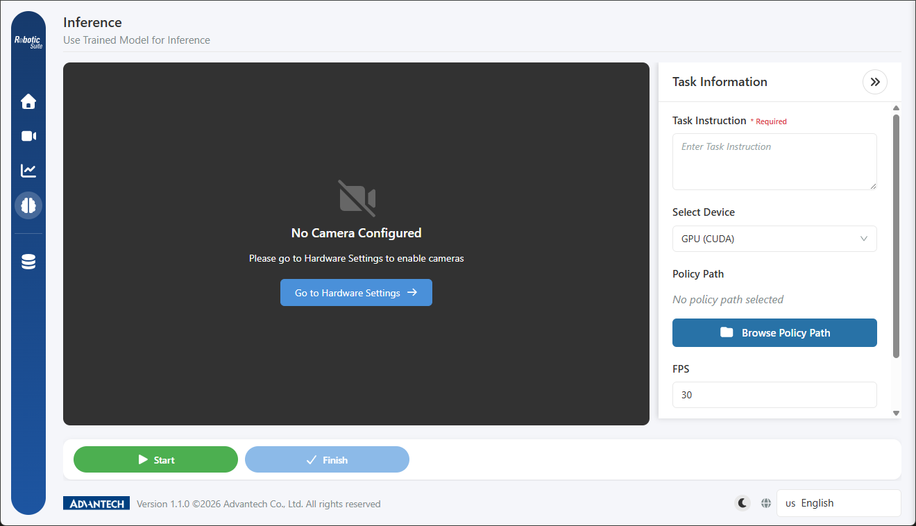
1. Layout and the transfer of roles
The layout of the inference page is identical to that of the recording page: camera imagery at the centre, the settings drawer on the right, and the control bar at the bottom. The purpose of this design is to permit direct comparison between the inference result and the demonstration under the same viewpoints and layout.
The two differ in the source of motion:
Recording:  human hand ──▶ Leader Arm ──▶ joint angles ──▶ Follower Arm
Inference:  model ───────────────────────▶ joint angles ──▶ Follower Arm
This also accounts for the hardware readiness check not examining the Leader Arm on the inference page: the operator's role has been assumed by the model, and only the camera and Follower Arm are required.
Camera placement must correspond to that used during recording The model learns the motion according to the viewpoints present during recording. If the top camera's position changes or the wrist camera's angle is altered, the input received by the model no longer corresponds to the training conditions.
Where verification results do not meet expectations, this is the item to be examined first.
2. Inference settings
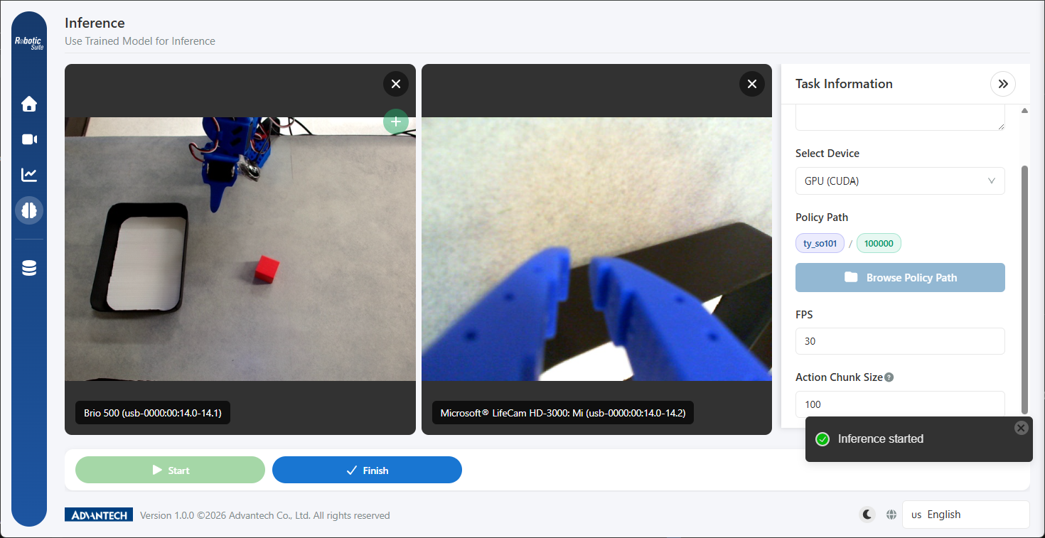
The drawer on the right contains five fields:
Task instruction (required). Equivalent in nature to the field completed during recording, and should correspond closely to the instruction used during training. Where GR00T N1.5 is used, this sentence constitutes an actual model input, and variation in its wording may produce differences in behaviour.
Device selection. Determines the execution environment of the model, and simultaneously determines whether model conversion is required; see section 3.
Policy path. Points to the model produced by training, selected by browsing via the folder button. Where the model has been transferred from another host, it must first be received through Model Management before selection.
Once selected, the screen marks the loaded model with two labels in the form "model name / step count". Where training has retained multiple progress saves, this constitutes the basis for distinguishing between them.
FPS. The control frequency of inference, which should correspond to the value used during recording. The model learns the motion at that frequency, and a change in execution frequency affects the temporal characteristics of the motion.
Action chunk steps. The interface describes this as: "each inference computes a segment of actions, then outputs them over several control cycles. A larger value produces a longer action segment per inference."
The mechanism is as follows: the model does not determine motion frame by frame, but plans a segment of the action sequence, executes it, and then plans the next segment.
- Lower values: the model re-observes and re-plans more frequently, responding more rapidly to variation, but at higher computational cost and with motion that may appear fragmented.
- Higher values: motion is more continuous and computational cost is lower, but no re-evaluation occurs before the segment completes, so environmental changes occurring mid-segment are not immediately reflected.
It is recommended that the default value be used for initial verification, with adjustment made only where a specific symptom is observed: reduce the value where motion is rigid or unresponsive to variation, and increase it where motion is fragmented or exhibits jitter.
Once inference has started, all fields within the drawer are locked as read-only. This is a safeguard, as parameter changes during inference directly affect a system actively controlling a physical arm. Inference should be stopped before any adjustment is made.
3. Device selection and conversion requirements
The device list on the inference page is more complete than that of the training page. Where the host is equipped with an NVIDIA GPU, four options are listed:
| Device | Applicable policy | Conversion required | Typical application |
|---|---|---|---|
| GPU (CUDA) | Both ACT and GR00T | No | Direct verification on the training workstation |
| CPU | ACT only | No | Basic verification on hosts without a GPU |
| GPU (OpenVINO) | ACT only | Yes; conversion to an OpenVINO model | Deployment to Intel platform edge devices |
| GPU (TensorRT) | GR00T only | Yes; conversion to a GR00T model | Deployment to edge platforms such as NVIDIA Jetson |
Where the host is not equipped with an NVIDIA GPU, the list contains only GPU (OpenVINO) and CPU.
This table corresponds to the binding relationship described in Policy Selection: runs trained with ACT are ultimately deployed to OpenVINO or CPU, and those trained with GR00T to TensorRT. No intersection exists between the two paths.
The recommended verification sequence is to verify first on GPU (CUDA) and to perform conversion subsequently. This sequence isolates the variables: direct execution on CUDA verifies the training effectiveness of the model itself, while execution after conversion verifies whether the conversion has affected performance. Where conversion is performed at the outset, the cause of any performance deficiency cannot be distinguished.
Switching devices clears the selected policy path. This is expected behaviour, as different devices require different model formats, and retaining the path from the previous device would result in a load failure. The path may simply be selected again.
4. Model conversion
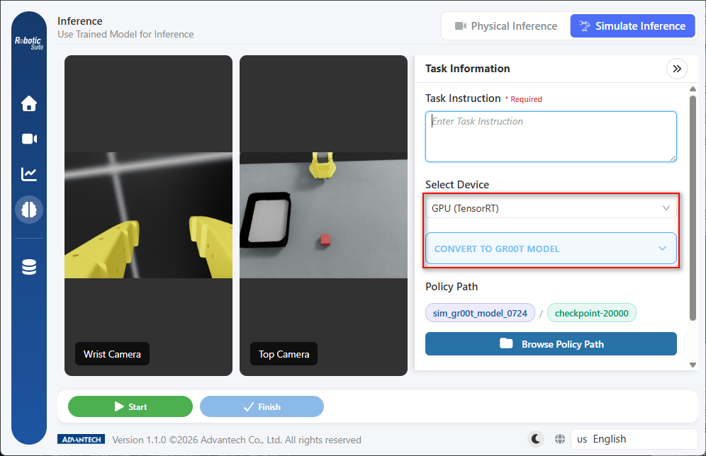
On selecting GPU (OpenVINO) or GPU (TensorRT), an expandable conversion section appears within the drawer, titled "Convert to OpenVINO model" and "Convert to GR00T model" respectively.
The figure below shows the state following selection of GPU (TensorRT), with the conversion section appearing directly beneath the device dropdown (outlined in red):
The nature of conversion
Conversion alters the manner in which the model is represented and executed so that it can run efficiently on the target hardware; the content learned by the model is unaffected.
Conversion therefore cannot remedy a model of insufficient training quality. Where a model exhibits accuracy deficiencies during verification on CUDA, conversion yields a model of equivalent accuracy that executes more rapidly. The model should be confirmed as viable before conversion is performed.
Procedure
- Expand the conversion section.
- Specify the output path using the folder button.
- Select "Convert model".
- Await completion. The status displays "Converting...", followed by a "Conversion complete" notification.
The page should not be navigated away from, nor the action repeated, during conversion. Once complete, the converted artifact may be used for inference verification.
5. Evaluation criteria for verification
Once inference has started, the robotic arm reproduces the learned motion autonomously. The evaluation criterion should be the degree of correspondence between the motion and the demonstration, rather than whether motion occurs.
Four specific items are to be evaluated:
First, task completion. Whether the object is grasped and placed in the correct position.
Second, correctness of the motion path. Whether the path corresponds to that of the demonstration. Path deviation generally reflects consistency issues in the demonstration data.
Third, alignment accuracy. The magnitude of alignment error between gripper and object.
Fourth, handling of undemonstrated positions. Move the object to a position not covered during demonstration and re-execute. This evaluation determines whether the model has genuinely learned to adjust its motion according to visual information, or has merely memorised a fixed trajectory.
A single result is insufficient as a basis for assessment; five to ten executions are recommended, with evaluation on the basis of success rate.
6. Failure diagnosis reference table
Where inference results do not meet expectations, the symptom may be traced to the corresponding stage:
| Symptom | Most probable cause | Corresponding chapter |
|---|---|---|
| No motion, or motion without discernible structure | Training did not converge; loss did not decline throughout | Loss interpretation in Training Monitoring; refer to Training Parameters where necessary |
| Motion corresponds but alignment error persists | Viewpoint issue; the model lacks the information required to determine precise position | Camera viewpoint design, particularly the placement of the wrist camera |
| Motion exhibits jitter or repeated correction | Hesitation and correction present in the demonstration data have been learned | Demonstration quality criteria; review each episode, remove the deficient ones, and retrain |
| Demonstrated positions succeed but new positions fail | Insufficient variation in the data; object position was fixed during demonstration | Physical recording or simulation SDG |
| Motion stops partway | Pauses present in the demonstration data have been learned | Physical recording; re-record the affected demonstrations |
| Performance is normal in simulation but deficient on physical hardware | The Sim-to-Real gap | The final section of Simulation; incorporate physical data |
| Normal on CUDA but anomalous after conversion | An issue in the conversion stage rather than the model itself | Section 4 of this chapter; repeat the conversion |
| No response; loading fails | Policy and device are incompatible, for example an ACT model with TensorRT | The binding relationship in Policy Selection |
This table should be used by first identifying the symptom and then tracing the corresponding stage. Of the eight symptoms listed, only one has its cause in the training parameters, whereas four originate in the data preparation stage.
7. Safety considerations
The arm moves autonomously during inference During inference, the motion of the robotic arm is determined by the model. Before starting, it must be confirmed that the arm's working envelope is clear and that personnel on site are aware that the arm is about to move autonomously.
For initial verification, personnel should be present to observe, with the ability to execute a stop operation at any time.
Next: Model deployment.