Arm Platforms & Serial Port Detection
Supported arm platforms
The platform supports two robotic arm families. They differ in motor ecosystem, connection method, and setup procedure, and the first step of configuration is therefore to confirm which model is in use.
| Item | OpenMANIPULATOR-X | SO-101 |
|---|---|---|
| Origin | ROBOTIS education / research | LeRobot open-source low-cost design |
| Motors | Dynamixel smart servos | Feetech servos |
| Connection | OpenRB-150 control board | One USB serial cable each for Leader and Follower |
| Automatic port identification | Supported (the control board carries a vendor identifier string) | Not supported (both present identically to the system) |
| Range calibration required | No (travel is defined at the factory) | Yes, for both Leader and Follower |
| Operations provided | Detect and connect, reset arm | Serial port detection, arm calibration, reset arm |
| Typical settings | Vocational education, research laboratories | Deployment evaluation, teaching, rapid prototyping |
The two requirements in the right-hand column define the applicable scope of the third section of this chapter and of Arm Calibration. OpenMANIPULATOR-X users need not perform either procedure.
How the model is determined
At startup the platform scans the host's serial device list: detection of an OpenRB-150 control board results in identification as OpenMANIPULATOR-X; absence of detection defaults to SO-101.
This is a one-directional determination based on identifier priority rather than a bidirectional detection. Where both hardware sets are connected simultaneously, or where the automatic result does not match the physical hardware, the model must be specified manually.
Specifying the model manually
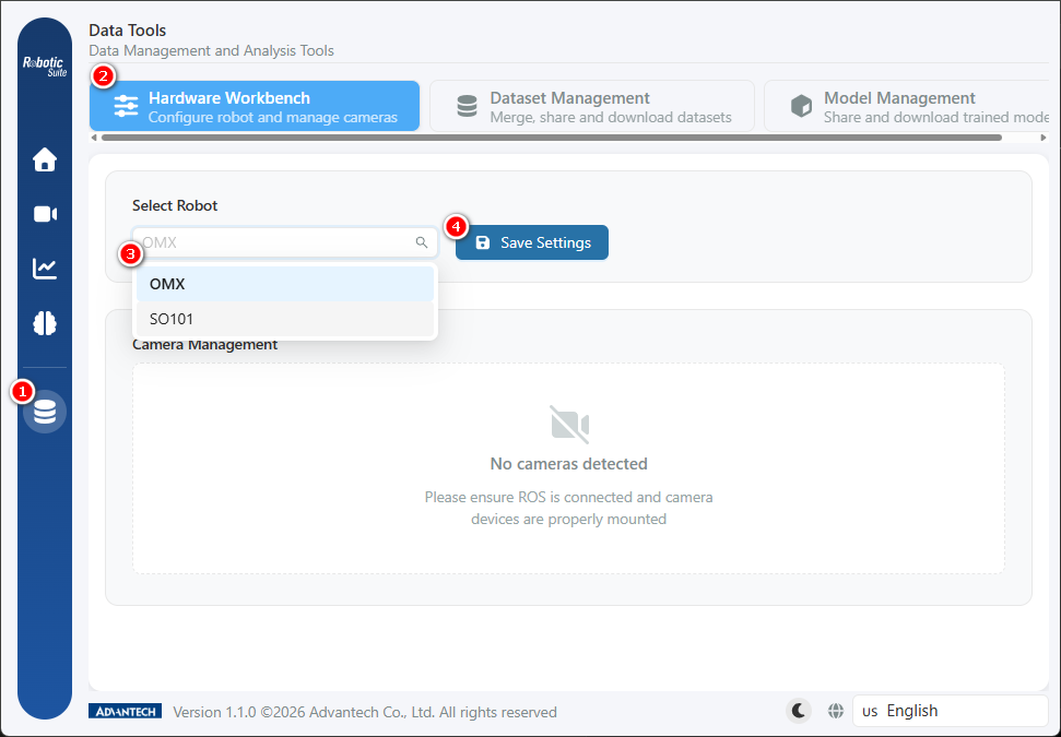
Follow the numbered steps in the figure above:
- Open Data Tools from the sidebar.
- Switch to the Hardware Workbench tab.
- Select the actual model from the "Select Robot" dropdown. The two options are labelled
OMXandSO101, corresponding to OpenMANIPULATOR-X and SO-101 respectively. - Click "Save Settings".
Once saved, the configuration status of the Leader and Follower appears to the right of the dropdown, together with the "Reset Robot Arm" and "Calibrate Arm" buttons:
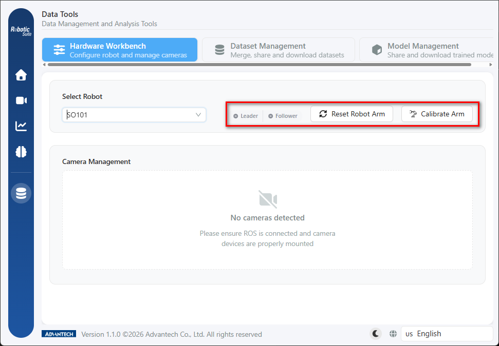
The subsequent controls do not appear before saving "Save Settings" must be clicked after switching models. Prior to saving, the "Reset Robot Arm" and "Calibrate Arm" controls outlined in red above remain hidden or disabled. This is a safeguard against operating one model's hardware using another model's configuration.
The Leader and Follower roles
Demonstration recording employs a Leader-Follower teleoperation architecture:
- Leader Arm (operator side): moved directly by hand, bearing no load, and responsible for converting operator intent into joint angle readings.
- Follower Arm (execution side): mirrors the Leader's joint angles in real time, physically contacting the workpiece and completing the task.
A necessary condition of this architecture is that the angle readings of both arms rest on the same baseline. If a given Leader pose is interpreted as a different angle on the Follower, every record captured will carry a constant offset. This is why calibration must be performed separately on both arms.
SO-101 serial port detection
Both SO-101 arms connect through generic USB serial chips and appear to the operating system as two identically presented device nodes. The platform encapsulates the identification procedure as a guided wizard.
Principle of identification
The system first records all currently present ports. After the operator disconnects the USB cable of one arm, a second scan is performed, and the difference between the two lists identifies the port corresponding to that arm.
Procedure
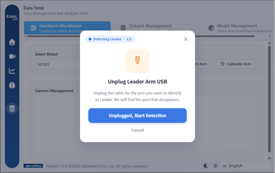
The wizard displays progress as a capsule in the upper left (Detecting Leader · 1/2 → Follower · 2/2):
- Confirm connection: both USB cables must be connected beforehand, as the comparison baseline is the complete port list.
- Guided disconnection: disconnect the cable of the arm to be designated as Leader, as prompted.
- Execute detection: once disconnected, click "Unplugged, Start Detection"; the system compares the two lists, typically completing within a few seconds.
- Result written: the detected port is written directly into the configuration field; no manual entry is required.
- Continue with the Follower: click "Detect Follower next →" to repeat the procedure, or select "Test Follower later" to exit temporarily.
Once detection of the Leader is complete, the Leader status marker on the "Select Robot" row turns to a green check, while Follower remains unconfigured. These two markers indicate the progress of detection:
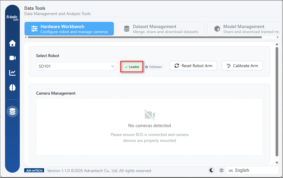
On completion, the wizard prompts for both arms to be reconnected to the host. The connection was genuinely disconnected during detection, and failure to restore it will cause subsequent calibration and recording to fail.
Handling an incorrect disconnection
If the Follower is disconnected during the step designating the Leader, the system cannot determine operator intent and will register the vanished port as the Leader according to the observed result, without reporting an anomaly. This results in the two arms' roles being interchanged, and the symptom can only be observed at the recording stage: moving one arm produces no corresponding response on the other.
The remedy is to execute serial port detection again; the existing configuration is overwritten, and no files require manual removal.
No device change detected
If no cable was actually disconnected, or an unrelated device was disconnected, the wizard reports "No Device Change Detected" and terminates detection, and the progress capsule in the upper left turns red:
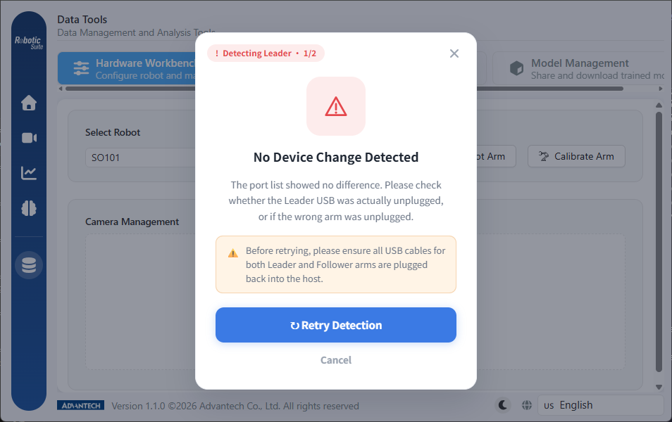
This case differs from the incorrect disconnection described above in that disconnecting the wrong arm does produce a change in the port list, and detection completes as normal without reporting an error. This screen appears only where the list is identical before and after.
Both USB cables must be reconnected to the host before "Retry Detection" is selected, so that the comparison baseline is the complete list.
The corresponding OpenMANIPULATOR-X procedure
OpenMANIPULATOR-X does not require serial port detection. Selecting "Detect and connect" in the hardware readiness notification causes the system to reset the arm and re-establish the connection with the OpenRB-150.
This is also the general purpose of the "Reset Arm" button: where an arm has lost its connection following a power interruption, cable reconnection, or service restart, the connection can be restored through this operation.
Next: SO-101 calibration.