Pose Estimation
Pose estimation converts an object detection result into a position and orientation that a robot can use.
Object perception may locate a target at pixel coordinates (u, v), but a robot arm operates in a 3D coordinate system. To connect these two representations, the system combines the detection result with depth data, camera calibration, and coordinate transformations.
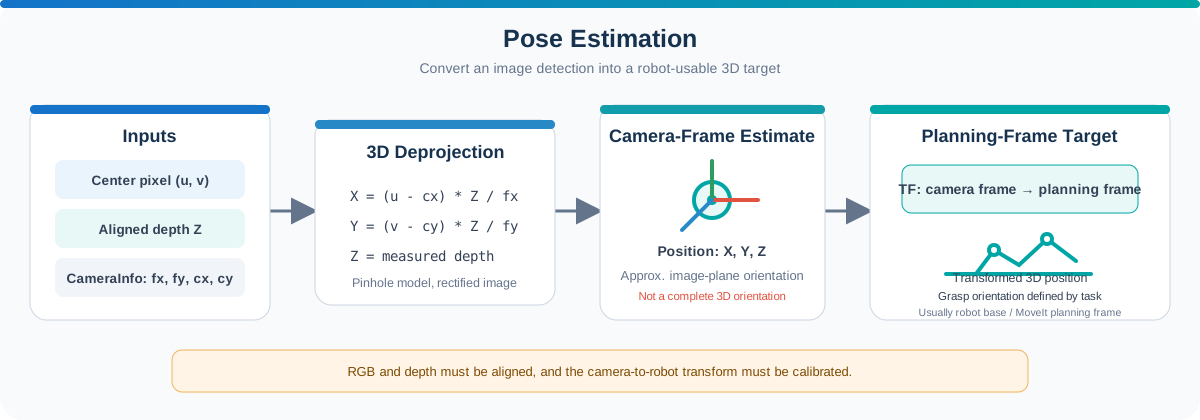
In a manipulation workflow, pose estimation answers questions such as:
- How far is the object from the camera?
- What is its 3D position in the camera frame?
- What is its orientation?
- Where is it relative to the robot base?
The resulting pose becomes a target for motion planning.
Role in a Manipulation Workflow
A typical pose-estimation workflow is:
2D detection → Depth lookup → 3D position in camera frame → TF transformation → Pose in robot base frame
The input usually contains:
- The target center or keypoints in the RGB image
- An aligned depth image
- Camera intrinsic parameters
- The coordinate transform between the camera and robot
The output is commonly represented as a 3D position and orientation associated with a coordinate frame and timestamp, for example using geometry_msgs/msg/PoseStamped.
Coordinate Systems
Manipulation systems use several coordinate systems, also called frames.
| Frame | Description |
|---|---|
| Image frame | A 2D pixel location such as (u, v) |
| Camera frame | A 3D position measured relative to the camera |
| Robot base frame | A 3D position measured relative to the robot base |
| End-effector frame | The position and orientation of the gripper or tool |
A position is meaningful only when its frame is known. For example, (0.3, 0.1, 0.6) in the camera frame does not describe the same physical location as the same values in the robot base frame.
ROS 2 uses TF to maintain the relationships between these frames.
From a Pixel to a 3D Position
An RGB image provides the horizontal and vertical pixel coordinates of an object, but it does not provide distance by itself. An RGB-D camera adds a depth value for each usable pixel.
For a detected center pixel (u, v), the pose-estimation process:
- Reads the depth value at or around the detected center.
- Validates that the depth is available and within the expected range.
- Uses the camera intrinsic parameters to project the pixel into 3D space.
For a rectified image using a pinhole camera model, the 3D position can be calculated as:
Z = depth
X = (u - cx) × Z / fx
Y = (v - cy) × Z / fy
Where:
fxandfyare the focal lengths in pixels.cxandcyare the principal-point coordinates.Zis the measured depth.X,Y, andZform the object position in the camera frame.
These intrinsic parameters are provided by camera calibration and are commonly published in ROS 2 through sensor_msgs/msg/CameraInfo.
RGB and Depth Alignment
The RGB and depth images must describe the same viewpoint before an RGB pixel can be used to read a depth value.
When depth is aligned to the RGB image, pixel (u, v) refers to the same scene point in both images. Without alignment, using the RGB coordinates directly in the depth image can produce an incorrect distance or select a neighboring object.
Camera drivers may provide an aligned depth topic directly. If not, registration must be performed using the calibration between the RGB and depth sensors.
Reliable Depth Sampling
The depth value at a single pixel may be missing or noisy, especially near object edges, reflective surfaces, or areas outside the sensor range.
Instead of relying on one pixel, a system can:
- Sample a small window around the detected center.
- Ignore zero, invalid, or out-of-range values.
- Use the median of the remaining depth samples.
- Reject the detection when too few valid samples remain.
The median is useful because it reduces the influence of isolated depth errors. The sampling window should remain small enough to avoid mixing the target with its background.
Estimating Orientation
A complete object pose includes both position and orientation.
The appropriate orientation method depends on the object and task:
- A rectangular contour can provide an approximate rotation in the image plane.
- Keypoints or geometric features can be used to estimate a more complete orientation.
- Fiducial markers can provide a known 6D pose.
- AI pose-estimation models can estimate orientation for more complex objects.
In the colored-block sample, the contour is used to estimate an approximate 2D yaw. This is useful for illustrating how the block is rotated in the image, but it is not a complete 3D orientation.
For a real grasping task, the system may also need to account for:
- The object surface normal
- The approach direction of the gripper
- Tool geometry and grasp offset
- Object symmetry
- Mechanical constraints of the robot
Camera-to-Robot Transformation
The position calculated from RGB-D data is initially expressed in the camera frame. Before motion planning, it must be transformed into a frame understood by the robot planning system, typically the robot base or planning frame.
The relationship between these frames must therefore be known:
Robot base frame
      ↕ TF
Camera frame
      ↓
Detected object pose
This relationship is determined through camera-to-robot calibration and published through TF. The system can then transform the detected object pose from the camera frame into the robot base frame.
Two common camera arrangements are:
- Eye-to-hand: The camera is fixed in the workspace. Its transform relative to the robot base is static.
- Eye-in-hand: The camera is attached to the robot. Its pose changes with the end effector and is resolved through the robot's TF tree.
An inaccurate camera transform causes a consistent offset between the detected position and the robot's actual target, even when the 2D detection and depth value appear correct.
Example: Colored-Block Position Estimation
The Robotic Suite sample combines color detection with aligned depth and camera information.
For each detected block, the node:
- Finds the block center in the RGB image.
- Reads valid depth samples near the center.
- Converts the pixel and depth into a 3D camera-frame position.
- Estimates an approximate image-plane yaw from the block contour.
- Displays or publishes the result for inspection.
This sample demonstrates the camera-side portion of pose estimation. To use the result with a physical robot arm, the application must also establish the camera-to-robot transform and convert the pose into the robot base frame.
See Color Block Detection & Position Estimation for the corresponding teaching sample.
Validating the Estimated Pose
Before using a pose as a motion-planning target, verify that:
- RGB and depth images are aligned and synchronized.
- The depth unit is interpreted correctly.
- Camera intrinsic parameters match the active image resolution.
- The source frame and timestamp are correct.
- The required TF transform is available.
- The transformed target lies inside the robot workspace.
- Position and orientation remain stable across several frames.
If the estimated position is incorrect, inspect the pipeline in order: detection center, depth value, camera intrinsics, depth alignment, and finally the camera-to-robot transform.
Key Takeaways
- In this RGB-D workflow, a 2D detection is combined with depth to obtain a 3D position.
- Camera intrinsics convert image pixels into points in the camera frame.
- RGB and depth alignment is required for correct depth lookup.
- TF transforms the camera-frame pose into the robot base frame.
- Image-plane yaw is only an approximate orientation, not a complete 6D pose.
- Pose quality must be validated before the robot is allowed to move.
Next: Use the target pose to generate a safe robot trajectory in Motion Planning.