Motion Planning
Motion planning converts a task goal into a robot trajectory that satisfies the configured kinematic, collision, and motion constraints.
After pose estimation, the system knows where the target object is relative to the robot. The robot must then determine how to move from its current configuration to the target without exceeding joint limits or colliding with itself and the environment.
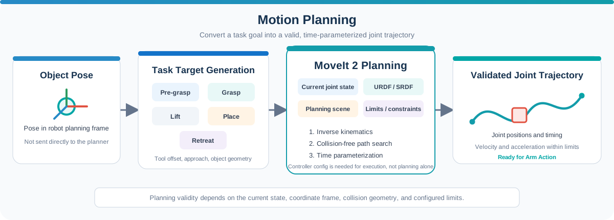
In a manipulation workflow, motion planning answers questions such as:
- Can the robot reach the target?
- What joint configuration should it use?
- How can it avoid collisions while moving?
- What approach and retreat motions are required?
- Is the generated trajectory valid for execution?
The resulting trajectory is passed to the Arm Action stage for execution and monitoring.
Role in a Manipulation Workflow
A typical planning workflow is:
Object pose → End-effector target → Inverse kinematics → Collision-free path → Time-parameterized trajectory
The planner normally requires:
- The robot's current joint state
- A robot model and planning configuration
- A target pose or joint-space goal
- Collision objects in the workspace
- Joint, position, orientation, and path constraints
The output is typically a joint trajectory containing joint positions and timing information, with velocity and acceleration values added when time parameterization is applied. Motion planning creates this trajectory; sending it to a controller and driving the physical joints are covered in Arm Action.
Robot Model and Planning Configuration
A planner needs an accurate model of the robot before it can evaluate reachability and collisions.
| Component | Purpose |
|---|---|
| URDF/Xacro | Describes robot links, joints, limits, and collision geometry |
| SRDF | Defines planning groups, end effectors, named states, and allowed collisions |
| Joint states | Describe the robot's current configuration |
| TF | Maintains the relationships between robot links and external frames |
| Kinematics configuration | Defines inverse-kinematics solvers and related search parameters |
| Execution / controller configuration | Defines how a planned trajectory is sent to the robot when execution is enabled |
Controller configuration is required for trajectory execution, but it is not required to compute a motion plan itself.
Visual meshes make the robot easy to recognize in RViz, while simplified collision geometry is commonly used for efficient collision checking.
The joint names and link names used by the robot driver, URDF, MoveIt configuration, and controller must be consistent.
From Object Pose to End-Effector Target
The detected object pose is usually not the pose that should be sent directly to the planner.
A manipulation application must convert the object pose into one or more target poses for the gripper:
object pose
    |
    +--> pre-grasp pose
    +--> grasp pose
    +--> lift pose
    +--> pre-place pose
    +--> place pose
    +--> retreat pose
These targets account for:
- The transform between the end effector and the tool center point
- The desired grasp direction
- Finger or gripper dimensions
- A safe approach distance
- Object dimensions and orientation
- The destination and stacking height
For example, the grasp pose may be centered on a block, while the pre-grasp pose is offset above it so the robot can approach in a controlled direction.
Inverse Kinematics
A Cartesian target describes where the end effector should be, but robot controllers move individual joints.
Inverse kinematics (IK) finds one or more joint configurations that place the end effector at the requested position and orientation.
An IK request can fail when:
- The target lies outside the robot's reachable workspace.
- The requested orientation cannot be achieved at that position.
- A required joint would exceed its limit.
- The solution is in collision.
- The solver cannot find a solution within its timeout.
Because a manipulator may have multiple IK solutions for the same target, the selected solution can affect path length, clearance, and proximity to singularities.
Planning with MoveIt
MoveIt 2 is a commonly used motion-planning framework for ROS 2 manipulators. It combines the robot model, current state, target, planning scene, kinematics, and planning algorithms.
A simplified MoveIt planning flow is:
- Read the latest robot state.
- Update the planning scene and collision objects.
- Define a pose goal or joint-space goal.
- Solve inverse kinematics when required.
- Search for a collision-free path through the robot's configuration space while satisfying the configured constraints.
- Time-parameterize the path using the configured velocity and acceleration limits.
- Return the trajectory for validation or execution.
MoveIt can use sampling-based planners such as those provided by OMPL. The appropriate planner and parameters depend on the robot, workspace, constraints, and task.
Planning Scene and Collision Checking
The planning scene represents the robot and its surroundings.
It can include:
- The robot's collision geometry
- A table, wall, fixture, or workcell boundary
- Objects that must be avoided
- Objects attached to the gripper
- Allowed collision relationships
Collision checking must include both:
- Self-collision: One robot link collides with another.
- Environment collision: The robot collides with an external object.
After grasping an object, the object should be attached to the end effector in the planning scene. This allows the planner to consider the carried object's size when planning the lift and transfer motions.
A planning scene is only as reliable as its input. Missing or inaccurate collision geometry can produce a mathematically valid path that is unsafe in the real workspace.
Constraints and Trajectory Limits
Motion planning must respect the physical and task-related limits of the system.
Common constraints include:
- Joint position limits
- Maximum joint velocity and acceleration
- End-effector position or orientation constraints
- Workspace boundaries
- A required approach direction
- Path constraints that must remain valid throughout the motion
After a geometric path is found, time parameterization assigns timestamps, velocities, and accelerations to its waypoints. These values must remain within the configured limits before the trajectory is sent to the controller.
Lower speed and acceleration scaling are useful during initial integration, but they do not replace collision checking or safety-rated hardware functions.
Example: Block Pick-and-Place Planning
In the colored-block workflow, pose estimation provides the target block position and an approximate orientation. The application then generates the required gripper targets.
A simplified sequence is:
- Transform the selected block pose into the robot base frame.
- Generate a pre-grasp pose above the block.
- Plan from the current state to the pre-grasp pose.
- Plan a controlled approach to the grasp pose.
- After the grasp succeeds, attach the block to the end effector in the planning scene.
- Plan a lift motion away from the workspace surface.
- Generate a place pose above the destination block.
- Plan the transfer, placement, and retreat motions.
- Plan a return motion to the waiting pose.
If a target is unreachable or planning fails, the application should not continue with the next motion as though the previous step succeeded. It should report the failure and move to a defined recovery or waiting state when safe to do so.
Understanding the Robotic Suite Sample
The original live manipulator demo used MoveIt to plan robot-arm motion from the detected block pose.
The downloadable offline sample is different: it replays previously recorded perception results, /joint_states, and TF data in RViz. It allows users to observe the workflow without the original camera or manipulator, but it does not calculate a new MoveIt plan during playback.
The sample therefore demonstrates how perception results and robot motion fit together, while a deployment on another manipulator still requires:
- A robot-specific URDF/Xacro and MoveIt configuration
- Correct kinematics and planning groups
- A camera-to-robot transform
- A planning scene matching the real workspace
- A compatible robot driver and trajectory controller
- Task logic for grasping, placing, failure handling, and recovery
See Manipulator for the recorded demonstration and integration overview.
Validating a Motion Plan
Before allowing execution, verify that:
- The start state matches the robot's current joint state.
- The target pose uses the expected coordinate frame.
- The IK solution respects all joint limits.
- The trajectory is collision-free in the current planning scene.
- Velocity and acceleration limits are satisfied.
- The end-effector approach and retreat directions are appropriate.
- The final pose and gripper clearance are suitable for the task.
- The planning result is still valid if the environment or target has changed.
RViz is useful for visualizing the robot model, target pose, planning scene, and planned trajectory before connecting the workflow to physical hardware.
Key Takeaways
- Motion planning converts a target into a collision-checked robot trajectory.
- An object pose must be converted into task-specific end-effector poses.
- MoveIt relies on an accurate robot model, current state, TF tree, and planning scene.
- IK determines whether a Cartesian target can be reached by valid joint positions.
- Collision checking must consider the robot, environment, and any carried object.
- The offline Robotic Suite sample replays recorded motion; it does not generate a new plan.
- A valid plan must be checked before it is sent to the robot controller.
Next: Send the validated trajectory to the controller and monitor its execution in Arm Action.