Arm Action
Arm action is the stage where a planned trajectory is sent to the robot and converted into physical joint motion.
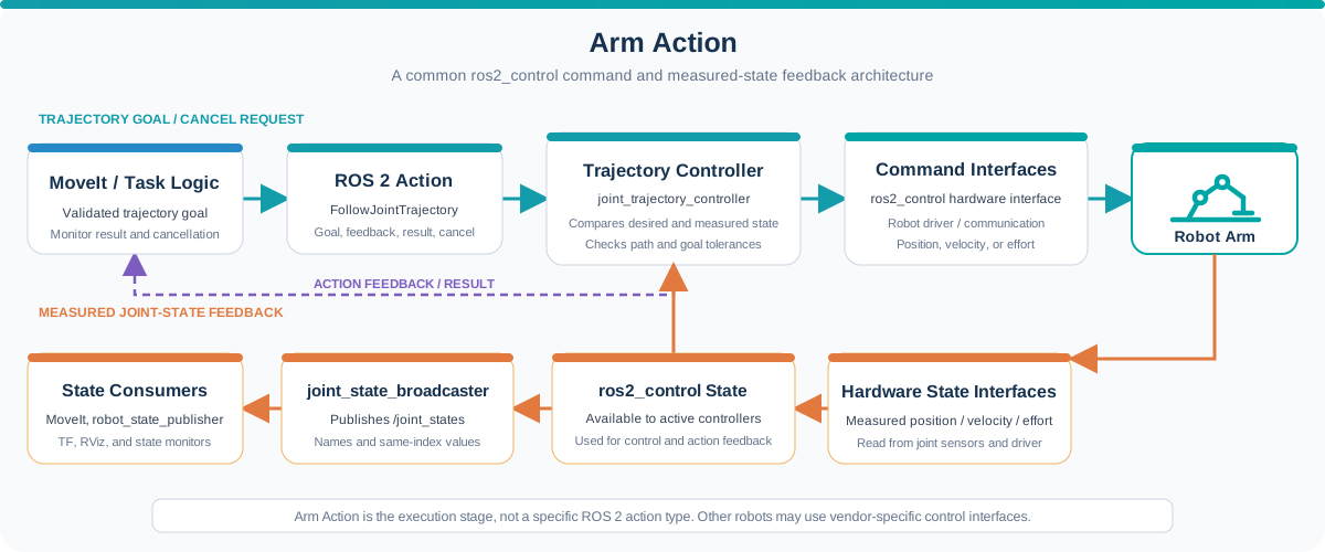
Here, "Arm Action" refers to the execution stage of the manipulation workflow, rather than to a specific ROS 2 action interface.
Motion planning determines how the robot should move. The action stage is responsible for commanding the controller, monitoring execution, coordinating the gripper, and reporting whether each motion succeeds or fails.
In a manipulation workflow, arm action answers questions such as:
- How is the planned trajectory sent to the robot?
- Is the robot following the requested motion?
- When should the gripper open or close?
- Did the motion finish successfully?
- What should happen if execution fails or is canceled?
The action stage closes the loop between software decisions and physical movement.
Role in a Manipulation Workflow
A common execution pipeline is:
Planned trajectory → Trajectory action → Robot controller → Hardware interface or driver → Joint motion
The feedback path returns the measured state through the control stack:
Joint sensors
        |
        v
Hardware interface / Robot driver
        |
        v
ros2_control state interfaces
        |
        +--> joint_trajectory_controller
        |        (measured joint state)
        |
        +--> joint_state_broadcaster
                  |
                  v
             /joint_states
                  |
                  v
       MoveIt and state monitors
The main inputs include:
- A validated joint trajectory
- The robot's current state
- Controller and hardware status
- Task commands for the gripper or other tools
The outputs include physical movement, execution feedback, and a final success or failure result.
ROS 2 Actions
Robot motions can take several seconds and may need feedback or cancellation. ROS 2 actions are designed for this type of long-running operation.
An action interaction contains:
| Part | Purpose |
|---|---|
| Goal | Describes the requested motion |
| Feedback | Reports progress while the motion is running |
| Result | Reports the final execution outcome |
| Cancel request | Requests that an active goal be stopped |
A common interface for manipulator trajectories is:
control_msgs/action/FollowJointTrajectory
Its goal contains a trajectory for a set of named joints. During execution, the controller can report desired and actual joint values as feedback and return a result when the goal finishes.
The exact interface depends on the robot driver and controller. Some systems expose a standard trajectory action, while others require a vendor-specific interface or an integration layer.
Trajectory Controllers and ros2_control
ros2_control provides a common framework for connecting ROS 2 controllers to robot hardware.
A typical manipulator control stack contains:
MoveIt or task application
        |
        v
FollowJointTrajectory action
        |
        v
joint_trajectory_controller
        |
        v
ros2_control hardware interface
        |
        v
Robot driver and actuators
The joint_trajectory_controller follows the requested joint positions over time. The hardware interface exposes the state and command interfaces supported by the robot and forwards controller commands to the underlying driver or hardware, such as position, velocity, or effort commands.
For successful integration:
- Joint names must match across the trajectory, controller, driver, and URDF.
- The controller must claim the required command interfaces.
- Joint-state feedback must use the expected joint names and units, and each value must correspond to the joint name at the same array index.
- Update rates and communication latency must be appropriate for the robot.
- The active controller must match the controller configured in MoveIt.
Not every robot uses ros2_control, but the same separation between planning, trajectory execution, and hardware communication still applies.
Joint-State Feedback
Execution should be monitored using measured robot state rather than assuming that a command was completed.
In ROS 2, joint feedback is commonly published as:
sensor_msgs/msg/JointState
The /joint_states topic may contain:
- Joint position
- Joint velocity
- Joint effort
- Timestamp
This feedback is used to update the robot state, generate the TF tree through robot_state_publisher, display the robot in RViz, and compare actual motion with the commanded trajectory.
A motion may be considered unsuccessful when:
- The controller rejects the goal.
- The robot cannot maintain the required path tolerance.
- The final joint error exceeds the goal tolerance.
- Communication with the robot is interrupted.
- Execution exceeds its timeout.
- A protective stop or hardware fault occurs.
Coordinating the Gripper
Pick-and-place tasks require arm motion and gripper action to be coordinated in the correct order.
A simplified sequence is:
- Move to the pre-grasp pose.
- Approach the object.
- Close the gripper.
- Confirm that the grasp succeeded when feedback is available.
- Attach the object in the planning scene.
- Lift and transfer the object.
- Move to the place pose.
- Open the gripper.
- Detach the object from the planning scene.
- Retreat from the placement area.
The gripper may use a standard action such as control_msgs/action/GripperCommand, a trajectory controller, digital I/O, or a vendor-specific command.
A close command does not always prove that an object was grasped. A complete system may use finger position, motor current, force sensing, vacuum pressure, or vision to confirm the result.
Task Sequencing
A manipulation task contains several dependent actions. Each step should begin only after the previous step has completed successfully.
The application can represent the workflow as states such as:
Waiting
  → Detecting
  → Planning
  → Moving to pre-grasp
  → Approaching
  → Grasping
  → Lifting
  → Moving to place
  → Releasing
  → Returning
  → Waiting
This makes it easier to:
- Track the current operation.
- Prevent commands from overlapping.
- Report progress to a user interface.
- Handle cancellation and timeouts.
- Return to a known state after a failure.
Task state and robot state should not be confused. A software state such as Grasping describes the current operation, while joint feedback describes the robot's measured physical configuration.
Failure Handling and Recovery
Execution failures must be handled explicitly. The application should not continue to the next step as if a failed motion succeeded.
Possible responses include:
- Stop the current task and report the error.
- Cancel the active trajectory when supported.
- Open or retain the gripper according to the physical situation.
- Re-read the current robot state before any new plan.
- Re-plan from the measured state.
- Move to a predefined recovery or waiting pose when it is safe.
- Require operator intervention after a protective stop or hardware fault.
Recovery behavior depends on the task. For example, opening the gripper automatically may be unsafe if the robot is holding an object above the workspace.
Broad retries without identifying the failure can create repeated unsafe motions. Retry limits and recovery conditions should therefore be defined as part of the task logic.
Safety Considerations
Planning and ROS-level control do not replace the robot's safety system.
A physical deployment must follow the robot manufacturer's instructions and may require:
- Emergency-stop circuits
- Protective stops and safety-rated monitored stops
- Joint, speed, force, and workspace limits
- Collision detection or torque monitoring
- Restricted operating zones
- Guarding, interlocks, or safety scanners
- Reduced-speed commissioning
- Operator procedures and risk assessment
RViz confirms the software's expected motion, not the safety of the real environment. Begin integration without payloads, use conservative limits, and keep the robot's hardware stop available.
Example: Executing the Block-Stacking Task
In the colored-block demo, the application executes a sequence based on the requested stacking order.
For each movable block, the system:
- Receives the validated pick-and-place trajectories.
- Sends the pre-grasp and approach motions to the arm controller.
- Waits for successful completion.
- Commands the gripper to grasp the block.
- Executes the lift and transfer motions.
- Places the block at the target stack position.
- Releases the block and retreats.
- Continues only when the previous operation succeeds.
After all blocks are placed, the arm returns to its waiting state. If a target is unreachable or an execution step fails, the application reports the error and follows its defined recovery behavior instead of continuing the stack.
Understanding the Robotic Suite Sample
The original live demo planned and executed motion on a manipulator. The downloadable offline sample does not command a physical controller.
The ROS bag contains recorded /joint_states, /tf, and /tf_static data, but there are two alternative ways to reproduce the robot TF tree.
Option 1: Generate TF from Recorded Joint States
Replay /joint_states and let robot_state_publisher calculate the link transforms from the robot model:
Recorded /joint_states
        |
        v
robot_state_publisher
        |
        v
Robot TF tree
        |
        v
RViz RobotModel movement
Option 2: Replay Recorded TF Directly
Replay the transforms captured from the original system:
Recorded /tf and /tf_static
        |
        v
Robot TF tree
        |
        v
RViz RobotModel movement
Only one source should publish the same transforms. Replaying recorded TF while robot_state_publisher publishes an identical TF tree can create duplicate or conflicting transform authorities.
Both options demonstrate the resulting arm motion and TF relationships, but neither provides:
- Live trajectory execution
- Controller feedback from a physical robot
- Gripper control
- Hardware fault handling
- Protective-stop integration
To control another manipulator, users must configure the corresponding driver, controller, command interfaces, feedback topics, safety behavior, and MoveIt execution settings.
See Manipulator for the recorded demonstration and integration overview.
Validating Arm Execution
Before running a task on physical hardware, verify that:
- The correct controller is active.
- Joint names and units match the robot model.
- The reported current state matches the physical robot.
- The robot is in the expected operating mode.
- Trajectory goals are accepted and feedback is available.
- Cancellation and timeout behavior work as intended.
- Gripper commands and grasp feedback are correct.
- Failures stop the task instead of advancing to the next step.
- Recovery behavior has been tested at reduced speed.
- Hardware safety functions remain active and accessible.
Monitor both software status and the physical robot throughout commissioning.
Key Takeaways
- Arm action converts a planned trajectory into monitored physical motion.
- ROS 2 actions support long-running goals, feedback, results, and cancellation.
- A trajectory controller and robot driver bridge MoveIt to the hardware.
/joint_statesprovides measured feedback for monitoring and visualization.- Arm and gripper commands must be coordinated as a stateful task sequence.
- Failures require explicit handling based on the robot's actual state.
- ROS software does not replace hardware safety functions.
- The offline Robotic Suite sample replays recorded motion rather than controlling a robot.
Arm action completes the manipulation pipeline:
Object Perception → Pose Estimation → Motion Planning → Arm Action