Color Block Detection & Position Estimation
This sample demonstrates how to detect colored blocks from an RGB-D camera and estimate their 3D position in the camera coordinate frame.
It is designed as the next step after Color Profile Creation. The previous tool creates HSV color profiles and saves them into color_profiles.json. This detector loads those HSV profiles, finds matching color regions in the RGB image, reads aligned depth data around each detected block center, and converts the 2D image position into a 3D position.
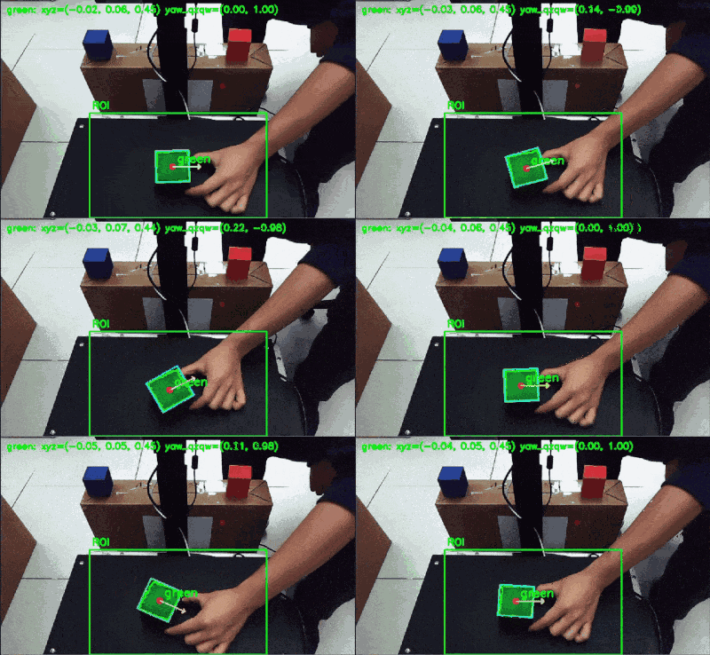
This is a teaching-oriented sample. The current implementation publishes the result as an
AprilTagDetectionArraymessage for compatibility with existing downstream workflows. The detected object is a color block, not a real AprilTag.
Overview
The detector performs the following steps:
RGB Image + Aligned Depth Image + CameraInfo
        |
        v
Load HSV profiles from color_profiles.json
        |
        v
Convert BGR image to HSV
        |
        v
Create color mask from HSV ranges
        |
        v
Apply ROI and contour filtering
        |
        v
Find block center in image coordinates
        |
        v
Read median depth around the center point
        |
        v
Convert pixel + depth to 3D camera-frame position
        |
        v
Estimate approximate 2D yaw from the contour
        |
        v
Publish debug image and detection result
What you will learn
After reading and running this sample, you will understand how to:
- Load HSV color profiles from a JSON file.
- Detect a selected color block using OpenCV color thresholding.
- Use
cv2.inRange()to create a binary mask. - Use
cv2.findContours()to find candidate block regions. - Filter detection results using ROI, contour area, and depth range.
- Use aligned depth data to estimate object distance.
- Use camera intrinsics from
CameraInfoto convert image coordinates into 3D coordinates. - Estimate an approximate yaw angle from a rotated rectangle.
- Publish a debug image and detection result for downstream robot-arm planning.
Relationship with Color Profile Creation
This sample depends on the output of the previous tool:
Color Profile Creation
        |
        v
color_profiles.json
        |
        v
Color Block Detection & Position Estimation
Expected JSON format:
{
  "profiles": {
    "blue": {
      "ranges": [
        {
          "lower": [95, 80, 60],
          "upper": [125, 255, 255]
        }
      ],
      "created_from": {
        "rgb_topic": "/camera/color/image_raw",
        "samples": 8
      }
    }
  }
}
Each profile contains one or more HSV ranges. Multiple ranges are useful for colors such as red, where the hue value may wrap around the OpenCV hue boundary near 0 / 180.
The detector automatically reloads color_profiles.json when the file modification time changes. This means you can update the profile file and continue testing without restarting the node.
Why HSV is used here
The detector does not compare raw RGB values directly. Instead, it converts the camera image to HSV and applies HSV thresholds from color_profiles.json.
HSV is useful because it separates color information from brightness:
| Channel | Meaning | Why it helps |
|---|---|---|
| H | Hue / color type | Helps identify the main color, such as red, green, blue, or yellow. |
| S | Saturation / color purity | Helps reject gray, white, or weak-color regions. |
| V | Value / brightness | Helps handle bright and dark regions of the same object. |
OpenCV uses the following HSV ranges:
H: 0 to 180
S: 0 to 255
V: 0 to 255
This is different from many online HSV tools, where Hue is often shown as 0 to 360 degrees.
Main processing flow
1. Subscribe to RGB, depth, and camera information
The node subscribes to three input topics:
| Input | Default topic | Purpose |
|---|---|---|
| RGB image | /camera/color/image_raw | Used for color detection. |
| Aligned depth image | /camera/aligned_depth_to_color/image_raw | Used to estimate distance. |
| CameraInfo | /camera/color/camera_info | Used to get camera intrinsics. |
The depth image should be aligned to the RGB image. This means the RGB pixel coordinate and depth pixel coordinate should refer to the same scene point.
2. Load the target color profile
The node loads HSV ranges from:
./color_profiles.json
By default, the target profile is:
blue
The target color can be changed by ROS 2 parameter:
-p target_color:=green
The node also supports:
-p target_color:=all
When target_color is set to all, the detector loads all profiles from the JSON file and tries to detect all configured colors.
3. Convert BGR image to HSV
OpenCV images are handled in BGR format. The detector converts the image to HSV before applying the color profile:
hsv = cv2.cvtColor(bgr_for_detection, cv2.COLOR_BGR2HSV)
Then each HSV range is applied with:
mask = cv2.inRange(hsv, lower, upper)
If a profile contains multiple ranges, the masks are merged using bitwise OR.
4. Apply ROI filtering
The detector applies a configurable region of interest in normalized image coordinates:
roi_x_min, roi_x_max
roi_y_min, roi_y_max
Default ROI:
x = 20% to 80% of image width
y = 48% to 100% of image height
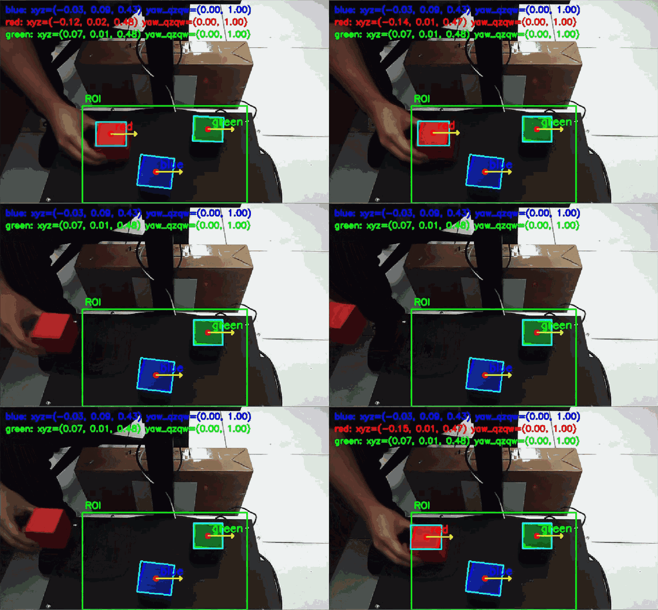
Only pixels inside this ROI are used for detection. This is useful for a robot-arm demo where blocks are placed on a table in a known working area.
The debug image draws the same ROI used by the algorithm, so users can clearly see where detection is active.
5. Find color regions
After creating the mask and applying the ROI, the node uses contours to find connected color regions:
contours, _ = cv2.findContours(mask, cv2.RETR_EXTERNAL, cv2.CHAIN_APPROX_SIMPLE)
Small regions are ignored using:
min_contour_area
This helps remove noise and tiny false-positive regions.
In target_color:=all mode, the detector also tracks used mask regions to reduce duplicated detections across different color profiles.
6. Estimate the block center
For each valid contour, the detector computes image moments and uses the contour center as the block center:
u = center x in image coordinates
v = center y in image coordinates
The center point is drawn on the debug image.
7. Read depth around the center point
Instead of using only one depth pixel, the node reads a small patch around the center point:
depth_patch_radius = 2
This means the default patch size is:
5 x 5 pixels
It filters invalid depth values and uses the median depth value.
This is more stable than using a single depth pixel, because depth images can contain noise or missing values.
The accepted depth range is configurable:
depth_min_m = 0.30
depth_max_m = 0.60
A detected block is ignored if its depth is outside this range.
8. Convert pixel and depth to 3D position
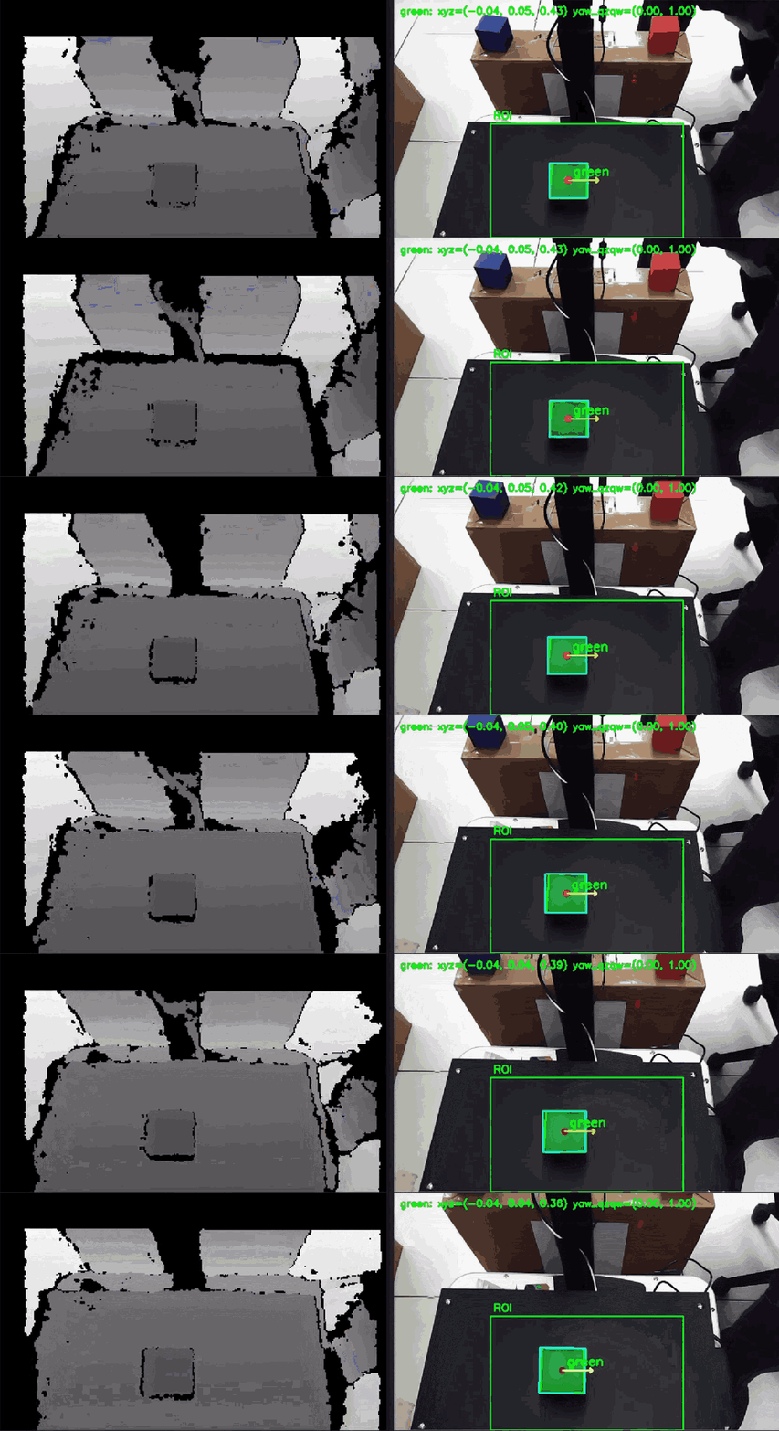
The detector uses the camera intrinsics from CameraInfo:
fx, fy, cx, cy
Then it converts the center pixel and depth into 3D camera-frame coordinates:
X = (u - cx) * Z / fx
Y = (v - cy) * Z / fy
Z = depth
Where:
| Symbol | Meaning |
|---|---|
u | Pixel x coordinate |
v | Pixel y coordinate |
Z | Depth in meters |
fx, fy | Camera focal length |
cx, cy | Camera optical center |
The output position is in the camera coordinate frame.
The published pose also adds a small configurable Z offset:
pose_z_offset_m = 0.03
This can be useful when the target pose should be slightly above the measured block surface.
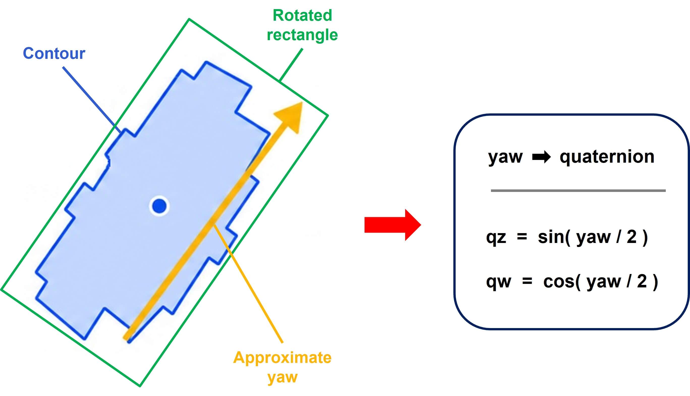
9. Estimate approximate 2D yaw
The node estimates an approximate 2D yaw angle from the detected contour using:
rect = cv2.minAreaRect(contour)
This creates a rotated rectangle around the contour. The yaw angle is estimated from the long side of that rectangle.
This is useful for teaching the idea of orientation estimation, but it is not a replacement for a full 6D object pose estimator.
The yaw angle is converted into a yaw-only quaternion:
qx = 0
qy = 0
qz = sin(yaw / 2)
qw = cos(yaw / 2)
10. Publish debug image and detection result
The node publishes:
| Output | Default topic | Purpose |
|---|---|---|
| Debug image | /color_block/debug_image | Shows ROI, contours, center points, rotated boxes, yaw arrows, and estimated position text. |
| Detection result | /tag_detections | Publishes detected block pose using AprilTagDetectionArray. |
The output parameter is named:
detection_topic
The default topic is still /tag_detections for compatibility with existing workflows.
How to run
1. Prepare a color profile
Run the Color Profile Creation tool first and save a profile file:
color_profiles.json
Make sure the profile name matches the target color used by this detector, for example:
blue
2. Start the RGB-D camera
Start your camera driver and make sure the following topics are available:
ros2 topic list
Expected topics:
/camera/color/image_raw
/camera/aligned_depth_to_color/image_raw
/camera/color/camera_info
3. Run the detector
Example:
python3 ros2_color_block_detector.py \
  --ros-args \
  -p rgb_topic:=/camera/color/image_raw \
  -p depth_topic:=/camera/aligned_depth_to_color/image_raw \
  -p camera_info_topic:=/camera/color/camera_info \
  -p profile_file:=./color_profiles.json \
  -p target_color:=blue
To detect all configured color profiles:
python3 ros2_color_block_detector.py \
  --ros-args \
  -p profile_file:=./color_profiles.json \
  -p target_color:=all
To adjust the detection ROI:
python3 ros2_color_block_detector.py \
  --ros-args \
  -p profile_file:=./color_profiles.json \
  -p target_color:=blue \
  -p roi_x_min:=0.20 \
  -p roi_x_max:=0.80 \
  -p roi_y_min:=0.48 \
  -p roi_y_max:=1.00
To adjust the valid depth range:
python3 ros2_color_block_detector.py \
  --ros-args \
  -p profile_file:=./color_profiles.json \
  -p target_color:=blue \
  -p depth_min_m:=0.30 \
  -p depth_max_m:=0.60
ROS 2 parameters
| Parameter | Default value | Description |
|---|---|---|
rgb_topic | /camera/color/image_raw | RGB image input topic. |
depth_topic | /camera/aligned_depth_to_color/image_raw | Aligned depth image input topic. |
camera_info_topic | /camera/color/camera_info | Camera intrinsics input topic. |
debug_image_topic | /color_block/debug_image | Debug image output topic. |
detection_topic | /tag_detections | Detection result output topic. |
target_color | blue | Target color profile name. Use all to detect all profiles. |
profile_file | ./color_profiles.json | Path to the HSV profile JSON file. |
depth_unit | mm | Depth image unit. Use mm for millimeters or m for meters. |
depth_min_m | 0.30 | Minimum valid depth in meters. |
depth_max_m | 0.60 | Maximum valid depth in meters. |
depth_patch_radius | 2 | Radius of the depth patch around the center point. 2 means a 5 x 5 patch. |
min_contour_area | 1000.0 | Minimum contour area used to filter small noise. |
roi_x_min | 0.20 | ROI left boundary, normalized by image width. |
roi_x_max | 0.80 | ROI right boundary, normalized by image width. |
roi_y_min | 0.48 | ROI top boundary, normalized by image height. |
roi_y_max | 1.00 | ROI bottom boundary, normalized by image height. |
output_frame_id | camera_link | Frame ID used in the published detection header. |
pose_z_offset_m | 0.03 | Z offset added to the published pose position. |
enable_preprocess | false | Enables optional image preprocessing for difficult . |
process_period_s | 0.05 | Processing timer period in seconds. |
Visualizing the result
You can view the debug image with rqt_image_view:
rqt_image_view /color_block/debug_image
The debug image shows:
- Detection ROI.
- Color contours.
- Detected color name.
- Center point of the block.
- Rotated rectangle around the contour.
- Yaw direction arrow.
- Estimated 3D position.
Example output concept
The detector publishes a message to the configured detection_topic.
Conceptually, each detection contains:
color name
image center point
2D rotated box corners
3D position: X, Y, Z
orientation: yaw-only quaternion
The current implementation stores the color profile name in:
det.family
For example:
family: blue
pose.position.x: X
pose.position.y: Y
pose.position.z: Z + pose_z_offset_m
pose.orientation.z: qz
pose.orientation.w: qw
Troubleshooting
No block is detected
Check:
- The
target_colormatches a profile name incolor_profiles.json. - The profile file path is correct.
- The block is inside the ROI.
- The contour area is larger than
min_contour_area. - The block is inside the valid depth range.
- The lighting conditions is similar to the one used during profile creation.
The debug image shows WAITING FOR DEPTH
This means the RGB image is received, but the depth image is not ready yet.
Check:
ros2 topic echo /camera/aligned_depth_to_color/image_raw --once
Also make sure the depth topic is aligned to the RGB image.
The debug image shows WAITING FOR CAMERA INFO
This means the node has not received camera intrinsics yet.
Check:
ros2 topic echo /camera/color/camera_info --once
The debug image shows NO VALID COLOR PROFILE
This usually means the profile file cannot be loaded or the target profile does not exist.
Check:
- The
profile_filepath. - The JSON format.
- The
target_colorname. - The top-level JSON field is named
profiles.
The position looks incorrect
Check:
- The depth unit is correct.
- The camera info topic matches the RGB camera.
- The depth image is aligned to the color image.
- The block center is not on an invalid or missing depth pixel.
- The target block is within
depth_min_manddepth_max_m.
Too many false detections
Try:
- Re-create the HSV color profile under the current lighting condition.
- Increase
min_contour_area. - Use a cleaner background.
- Reduce the HSV margins in the color profile.
- Limit detection to a smaller ROI.
- Try
enable_preprocess:=trueif lighting is difficult.
Notes for teaching
This sample is useful for explaining the perception part of a robot-arm workflow:
Color Profile
    -> HSV Color Detection
    -> Contour Filtering
    -> Center Point Estimation
    -> Depth Lookup
    -> 3D Position Estimation
    -> Approximate Orientation Estimation
    -> Robot Arm Planning
It is intentionally simple and easy to modify. For more advanced use cases, you may want to add:
- Better synchronization between RGB and depth images.
- Morphological operations for mask cleanup.
- More robust contour filtering.
- A custom detection message instead of
AprilTagDetectionArray. - Full 6D pose estimation.
- TF transform from camera frame to robot base frame.
Next step
The estimated 3D position and yaw orientation can be sent to a motion-planning module such as MoveIt.
In a robot-arm demo, this allows the system to:
- Detect the requested color block.
- Estimate the block pose.
- Send the target pose to the planner.
- Move the robot arm to pick or stack the block.