1 Product Introduction
ASR-D501 is an ARM-based single-board computer powered by the Qualcomm® Dragonwing™ QCS6490 platform.
Designed as a companion computer for drones, it combines low-power edge AI processing with rugged onboard memory and storage.
This document explains how to use ASR-D501 I/O with Ubuntu.
| Model Name | ASR-D501-N1A1U |
|---|---|
| Processor | Qualcomm® QCS6490 |
| AI Computing Power | 12 TOPS (NPU) |
| Memory | Onboard 8 GB LPDDR5 |
| OS Storage | Onboard 128 GB UFS |
| Operating System | Ubuntu 24.04-x07 |
1-1 Product Features
- Qualcomm QCS6490 with 8-core Kryo 670 CPU, Adreno 643 GPU, and up to 12 TOPS NPU
- Onboard 8 GB LPDDR5 memory and 128 GB UFS storage
- Extended operating temperature from -20°C to 70°C
- Mini DisplayPort, 1x 2.5 GbE, 2x CAN FD, 2x USB Type-C, 2x I2C, 3x UART, and 5 x MIPI CSI
- 1x M.2 Key-E and 1x M.2 Key-B expansion
- Compact 100 x 60 mm form factor, 50g net weight without heatsink
- Ubuntu support with compatible ROS2 and MAVLink, MAVROS, and MAVSDK workflows
- Qualcomm® Trusted Execution Environment (TEE) v5.3 onboard security
1-2 Official Website
2 Mechanical and Environmental
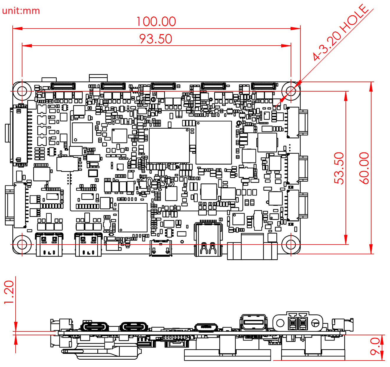
2-1 Layout and Sizes
ASR-D501 single board.
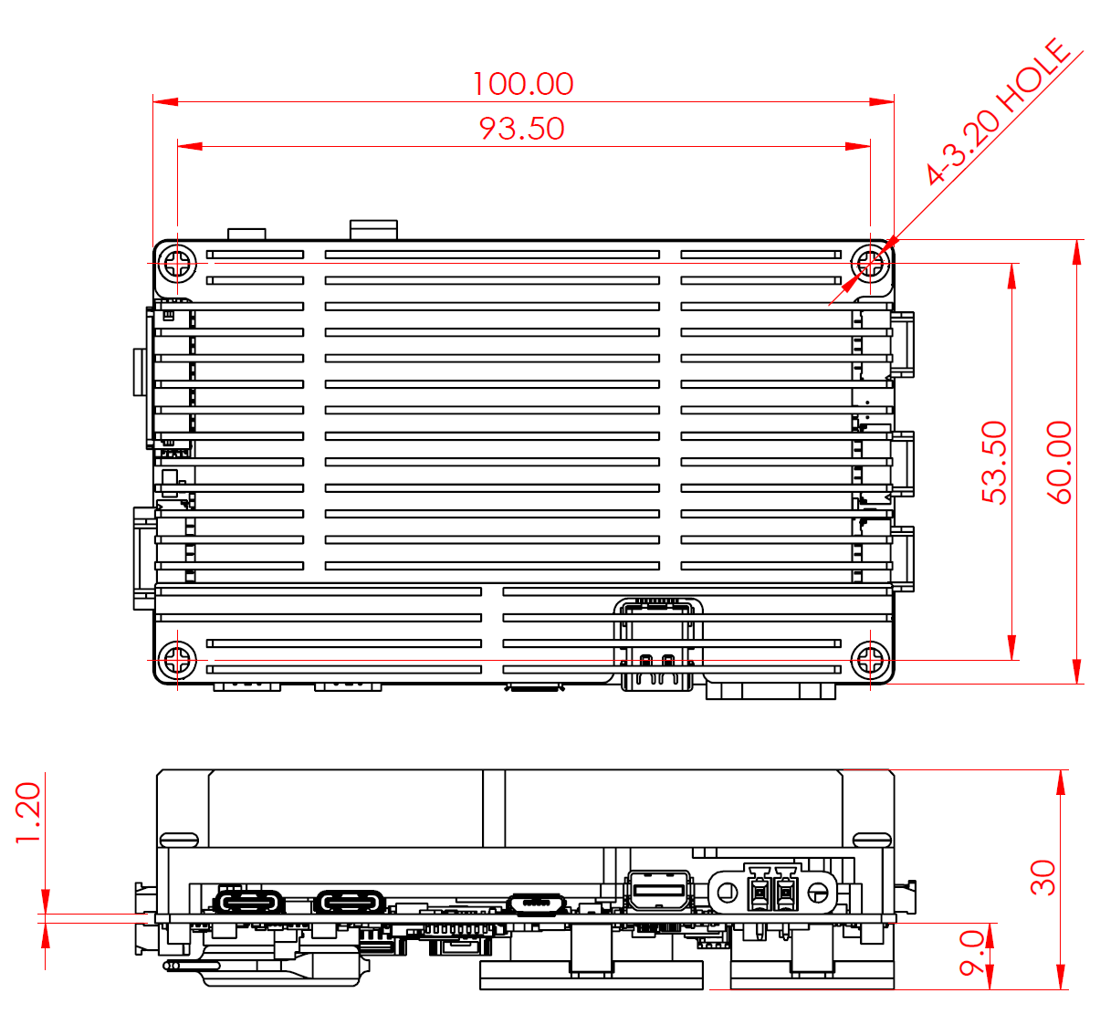
ASR-D501 with heatsink.
2-2 Thermal Solution
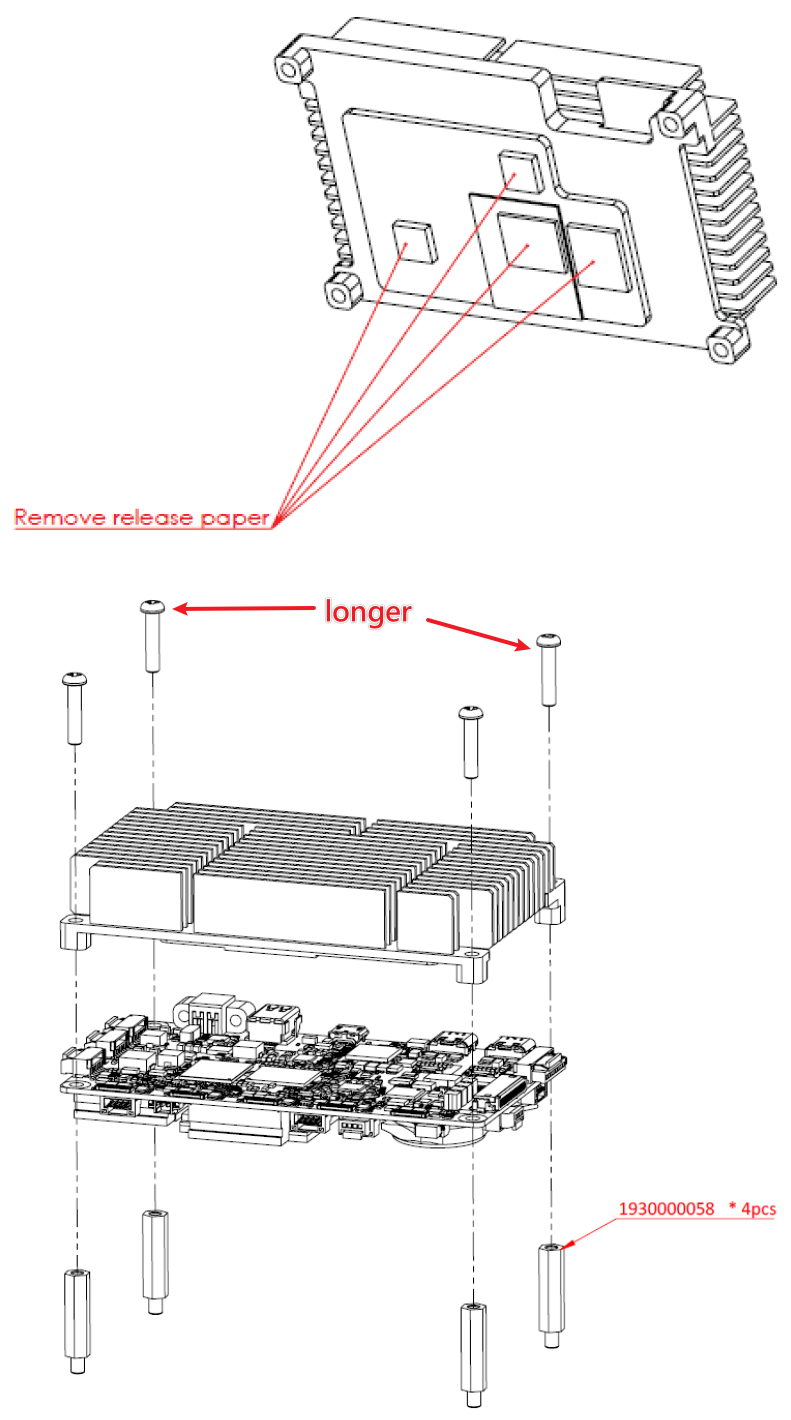
There is a passive heatsink in the package which could be secured to the board with four screws.
The working temperature of ASR-D501 is -20°C ~ 70°C (measured with 0.7 m/s airflow).
Remove the release paper from the thermal pads before installing the heatsink, then fasten the four screws as shown below.
There is an optional fansink for ASR-D501, which will connect FAN1 connector for power supply.
3 Hardware Interface Introduction
3-1 Switch and Jumper
Please refer to the following image for the switch location.
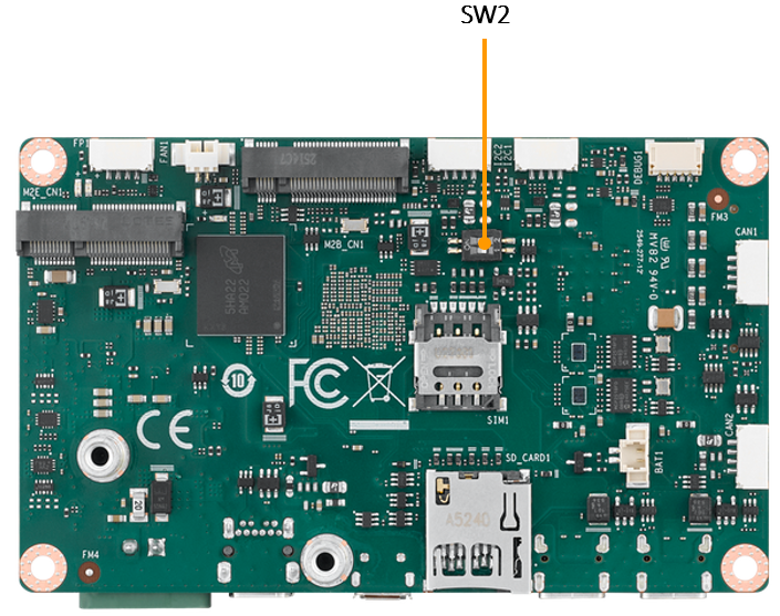
| SW2 | ON | OFF |
|---|---|---|
| Pin1 | EDL Mode (for image flashing) | Normal Boot Up |
| Pin2 | Auto Power On | Power On by Power Button |
3-2 Connector Introduction
Please refer to the following images for the I/O connectors. Pin definitions are available in the ASR-D501 User Manual.
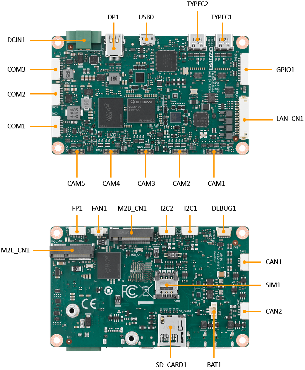
| Name | Description |
|---|---|
| DCIN1 | DC input connector |
| DP1 | Mini DisplayPort |
| USB0 | MicroUSB Connector for image flashing only |
| TYPEC1 / TYPEC2 | USB Type-C connectors |
| GPIO1 | GPIO connector |
| LAN_CN1 | LAN connector |
| CAM1-CAM5 | MIPI CSI camera connectors |
| COM1-COM3 | UART connectors |
| FP1 | Front-panel connector |
| FAN1 | Fan connector |
| M2B_CN1 | M.2 Key B connector |
| I2C1 / I2C2 | I2C connectors |
| DEBUG1 | Debug connector |
| CAN1 / CAN2 | CAN bus connectors |
| BAT1 | RTC battery connector |
| SD_CARD1 | SD card slot |
| M2E_CN1 | M.2 Key E connector |
| SIM1 | SIM card slot |
4 Operating System
4-1 Image Download
Refer to the BSP Launcher User Guide to download and install the BSP Launcher for obtaining ASR-D501 Ubuntu image.
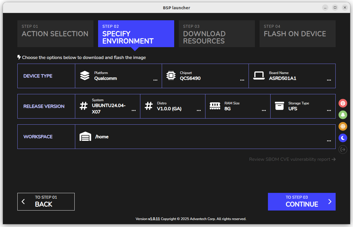
4-2 Flashing Image
Power off ASR-D501, set SW2 Pin1 to ON and power on for entering EDL mode, then connect the ASR-D501 Micro USB (USB0) to the host computer with a data-capable USB cable.
Follow the BSP Launcher User Guide to flash a pre-built image or image built from BSP into the ASR-D501.
After flashing done, cut off the power and set SW2 Pin1 back to OFF, power on again, ASR-D501 should boot into Ubuntu Desktop within 2 minutes.
4-3 BSP Download
| Image Version | Release Date | Image Download | BSP Download | Comment |
|---|---|---|---|---|
| Ubuntu 24.04-x07 v1.0.0 | 2026-07-08 | Download | Download | kernel 6.8.0-1057 |
5 Operating Method
5-1 Account and Password
The default account and password for ASR-D501 are ubuntu / ubuntu.
User can run the following commands to change the default root and user password.
$ sudo passwd root
$ sudo passwd ubuntu
5-2 USB Type-C Connectors
Based on ASR-D501 hardware design, if the Micro USB (USB0) is connected to the host, the both USB Type-C will be disabled.
Please disconnect the Micro USB (USB0) to enable the USB Type-C (TYPEC1 and TYPEC2).
5-3 General-Purpose Input / Output (GPIO)
ASR-D501 provides 8 pins 3.3V application GPIO signals. The GPIO pin definition is shown as below.
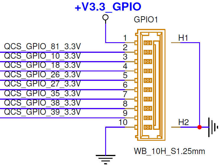
The following mapping applies to the optional GPIO cable that converts the onboard 10-pin GPIO1 header to a DB9 connector.
The onboard GPIO1 connector also provides a 3.3V supply pin, but the DB9 mapping below does not expose that supply.
| DB9 Pin | Single Pin | SYSFS Pin | Chip, Line in GPIOD |
|---|---|---|---|
| 1 | GND | - | - |
| 2 | GPIO_81 | 616 | 3, 81 |
| 3 | GPIO_10 | 545 | 3, 10 |
| 4 | GPIO_18 | 553 | 3, 18 |
| 5 | GPIO_26 | 561 | 3, 26 |
| 6 | GPIO_27 | 562 | 3, 27 |
| 7 | GPIO_35 | 570 | 3, 35 |
| 8 | GPIO_38 | 573 | 3, 38 |
| 9 | GPIO_39 | 574 | 3, 39 |
The following steps show how to control GPIOD.
First example is reading level value from GPIO_81, gpioget will set the GPIO pin to input.
$ sudo gpioget 3 81Next example is setting GPIO_81 to high or low level, =1 for high and =0 for low.
$ sudo gpioset 3 81=1
$ sudo gpioset 3 81=0
5-4 Ethernet Intel I226-V
ASR-D501 provides a 2.5 GbE interface. Its name is enP1p1s0. Use the following command to check the link state.
If enP1p1s0 is not exist, please check its actual name by ip link command.
$ ip link show enP1p1s0The LED behavior on the Ethernet cable is shown as below.
| LED | Status | Description |
|---|---|---|
| Link LED | Green | 2.5 GbE link established |
| Link LED | Orange | 1 GbE link established |
| Activity LED | Blinking | Network traffic present |
5-5 MIPI Camera
ASR-D501 supports 5 MIPI CSI camera connectors. Camera modules, cable orientation, device-tree support, and camera index must match the selected BSP release. The camera connector mapping is shown as below.
| Camera Connector | Reference Sensor |
|---|---|
| CAM1 | IMX577 |
| CAM2 | IMX577 |
| CAM3 | OV9282 |
| CAM4 | OV9282 (IFE_LITE) |
| CAM5 | OV9282 (IFE_LITE) |
5-5-1 Camera Pre-Setting
Perform each preparation step before starting a camera pipeline.
These settings are not persistent after device reboot, run commands again for cameras after restarting the board.
1. Enter root shell
$ sudo -s2. Set the governor to performance
# echo performance > /sys/devices/system/cpu/cpu*/cpufreq/scaling_governor3. Set CPU cluster frequency limits
# for cpu in $(seq 0 7) ; do \
      cd /sys/devices/system/cpu/cpu${cpu}/cpufreq ; \
      cp scaling_max_freq scaling_min_freq ; \
  done
# for cpu in 0 4 7; do \
      cd /sys/devices/system/cpu/cpufreq/policy${cpu} ; \
      cp scaling_max_freq scaling_min_freq ; \
  done
4. Disable CamX system logging
# echo "systemLogEnable=FALSE" > /var/cache/camera/camxoverridesettings.txt5. Restart the camera service
# systemctl restart cam-server5-5-2 Camera Stream Commands
Open a new terminal and run the following commands for viewing the video stream from cameras.
Camera indices are dynamically allocated based on active connections rather than physical port positions.
For instance, with an IMX577 on CAM1, its index is 0. If CAM2 is unused, it does not occupy an index, making the OV9282 on CAM3 be assigned index 1. Thus, if no IMX577 is connected, index 0 will be assigned to the first connected OV9282 camera among CAM3 through CAM5.
$ gst-launch-1.0 -e qtiqmmfsrc name=camsrc camera=0 ife-direct-stream=0 ! video/x-raw,format=NV12,width=1280,height=720,framerate=30/1 ! waylandsinkPlease modify camera=0 to target camera index, other parameters can be modified to meet the requirement of the application.
| Parameter | Description |
|---|---|
gst-launch-1.0 | Starts a GStreamer pipeline from the command line. |
-e | Sends an end-of-stream event when the pipeline is stopped, allowing resources to close cleanly. |
qtiqmmfsrc | Qualcomm camera source provided by the ASR-D501 BSP. |
name=camsrc | Assigns the name camsrc to the camera source element. |
camera=0 to 4 | Selects the BSP camera index corresponding to number of connected cameras (CAM1 through CAM5). |
ife-direct-stream=0 or 1 | Disable / Enables the direct Image Front End stream required by CAM3 to CAM5 reference configuration. |
! | Connects one GStreamer element or capability filter to the next. |
video/x-raw | Requests uncompressed raw video output. |
format=NV12 | Selects the NV12 YUV 4:2:0 pixel format. |
width=1280,height=720 | Requests a 1280 x 720 output resolution. |
framerate=30/1 | Requests 30 frames per second. |
waylandsink | Displays the video in the Ubuntu Wayland desktop session. |
5-6 Universal Asynchronous Receiver / Transmitter (UART)
ASR-D501 provides 3 UART interfaces. Run the following command to confirm the device nodes supplied by the installed BSP.
$ ls -l /dev/ttyHS*| Port | UART Device |
|---|---|
| COM1 | /dev/ttyHS1 |
| COM2 | /dev/ttyHS2 |
| COM3 | /dev/ttyHS3 |
The onboard COM connectors expose 0-3.3V TTL UART.
They are not conventional RS-232 COM ports and must not be connected directly to equipment using RS-232 voltage levels, which can approach positive and negative 15 V. Use an appropriate external transceiver for RS-232, RS-422, or RS-485 equipment.
Follow the steps below to configure COM1 at 115200 baud.
$ sudo -s
# stty -F /dev/ttyHS1 115200 raw -echo -onlcr
# echo "COM1 send data" > /dev/ttyHS1
# cat /dev/ttyHS1
echo "data" > is using target port to send data.
cat is used to display received data on the terminal until press Ctrl+C to stop it.
Configure COM2 by replacing /dev/ttyHS1 with /dev/ttyHS2. For COM3, use /dev/ttyHS3.
5-7 Front Panel (FP)
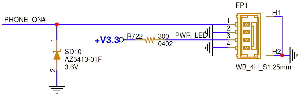
The Pin 1 PHONE_ON# signal is active-low and can be used to trigger a power-on event when it is shorted to ground.
The Pin 3 provides a 3.3V supply for powering an external LED, which indicates the power state of the board.
5-8 Wireless Communication Module
5-8-1 5G Module
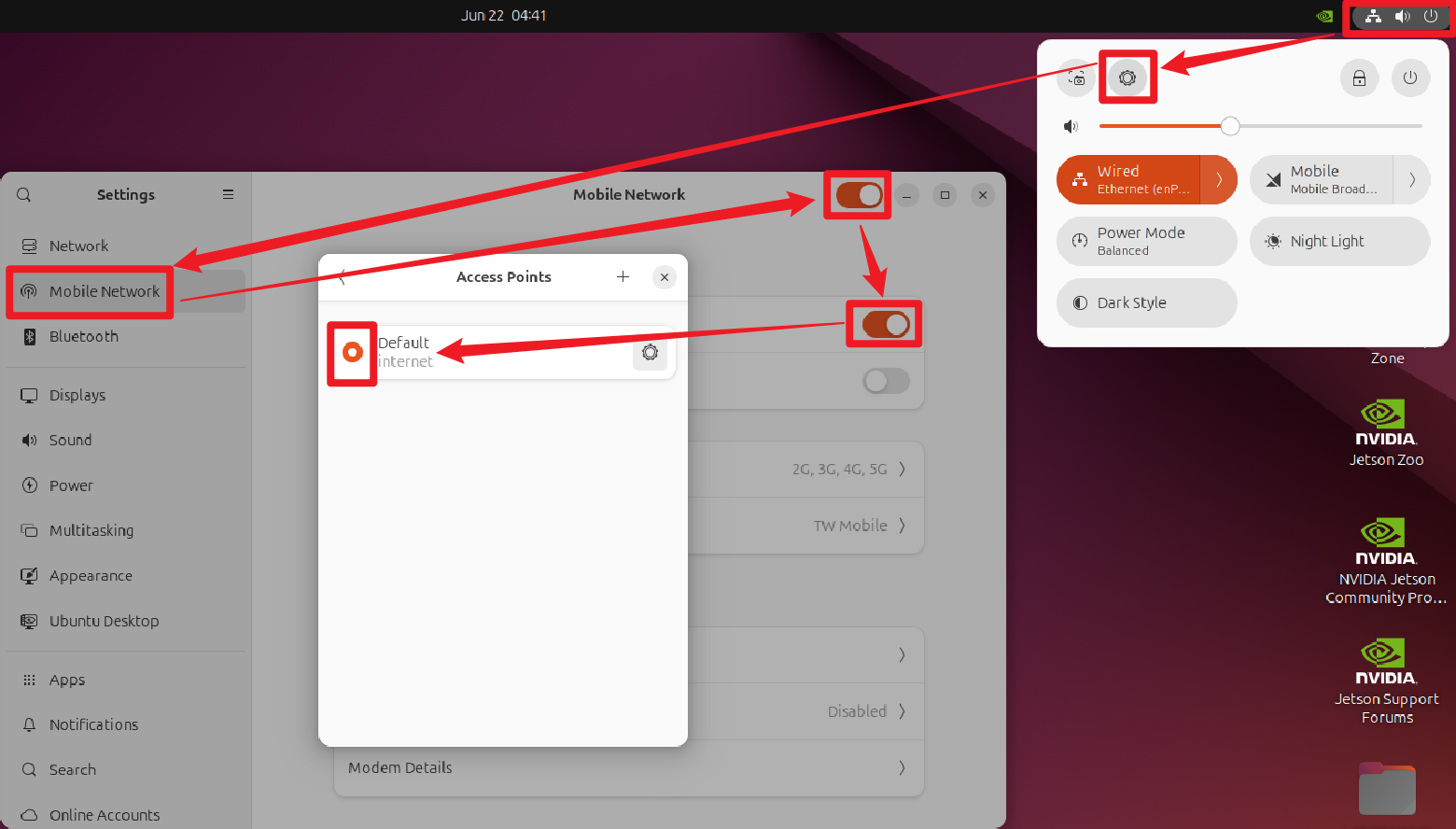
ASR-D501 supports the AIW-356 (M.2 Key-B) 5G module. Insert the Nano-SIM before booting.
After the modem enumerates, use Ubuntu Settings or NetworkManager to configure the carrier connection.
5-8-2 Wi-Fi and Bluetooth Module
ASR-D501 supports the AIW-170 (M.2 Key-E) Wi-Fi and Bluetooth module. The driver has been integrated into the Ubuntu image.
If AIW-170 is connected, use the following commands to verify the Wi-Fi interface and Bluetooth controller.
$ nmcli device wifi list
$ bluetoothctl show
5-9 Inter-Integrated Circuit (I2C)
ASR-D501 provides 2 external I2C connectors and there are 2 internal I2C buses, the connector bus numbers shown as follows.
| Bus | Function |
|---|---|
| /dev/i2c-1 | Internal I2C |
| /dev/i2c-3 | Internal I2C |
| /dev/i2c-9 | I2C connector 1 |
| /dev/i2c-2 | I2C connector 2 |
Scan the connected I2C devices by following command with the Bus index, for instance, 9 means I2C connector 1.
$ sudo i2cdetect -y -r 9The bus number can differ by BSP release. Confirm it with sudo i2cdetect -l before using an external I2C device.
5-10 Debug UART
The Debug UART is 0-3.3V TTL UART, must not be connected directly to equipment using RS-232 voltage levels.
Use the UART to RS-232 converter with DEBUG1 and below settings for accessing the maintenance console. The connector TX to host RX, connector RX to host TX, and GND to GND.
| Setting | Value |
|---|---|
| Baud Rate | 115200 |
| Data Bits | 8 |
| Stop Bits | 1 |
| Parity | None |
| Flow Control | None |
5-11 CANBUS
ASR-D501 provides 2 CAN interfaces, can0 and can1. The hardware between 2 CAN devices will be CANH to CANH, CANL to CANL, GND to GND.
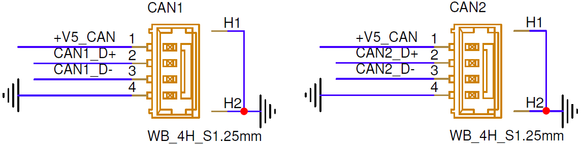
Install the CAN utility and run the following commands to set arbitration bitrate and data bitrate to the CAN bus.
$ sudo apt install -y can-utils
$ sudo ip link set can0 up type can bitrate 1000000 dbitrate 8000000 fd on
$ sudo ip link set can1 up type can bitrate 1000000 dbitrate 8000000 fd on
Receive data from CAN bus by candump command.
$ candump can1Send data to CAN bus by cansend command. Below 2 examples indecate standard CAN message format and CAN-FD message format.
$ cansend can0 111FFFFF#aa.00.cc.aa.33.61.aa.ab
$ cansend can0 123##1AABBCCDDEEFF00112233445566778899
Another method, use cangen to generate random standard CAN messages, or add -f for random CAN-FD messages.
$ cangen can0
$ cangen -f can0
5-12 Micro SD Card
Insert a microSD card to SD_CARD1, Ubuntu will mount it to /media/ubuntu/ automatically, check it by lsblk command.
$ lsblkRemeber to unmount the MicroSD card before unplug it.
$ sudo umount /media/ubuntu/*