1 Product Introduction
The AFE‑A702 is using the ASR‑A702 as its motherboard.
This document will share how to use AFE-A702/ASR-A702 with Ubuntu 24.04.
Platform: Jetson Thor
1-1 Product Features
- Ubuntu 24.04 validation ready
- Peripheral interface function verification
- Network, display, storage, and expansion interface validation
- Suitable for robotic / edge AI application validation workflow
- Supports Advantech Robotic Suite integration workflow
1-2 Official Website
2 Hardware Interface Introduction
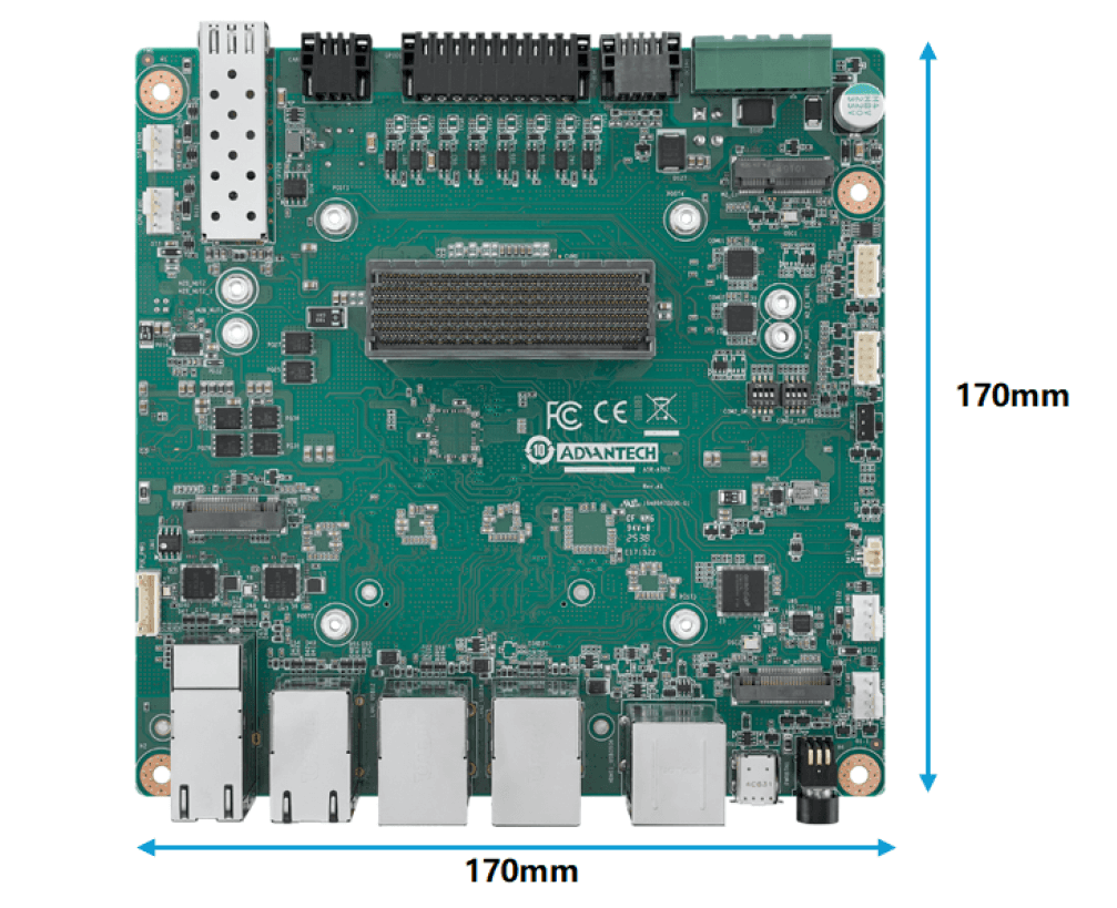
2-1 Layout and Sizes
- ASR-A702/AFE-A702 series
2-2 Switch and Jumper
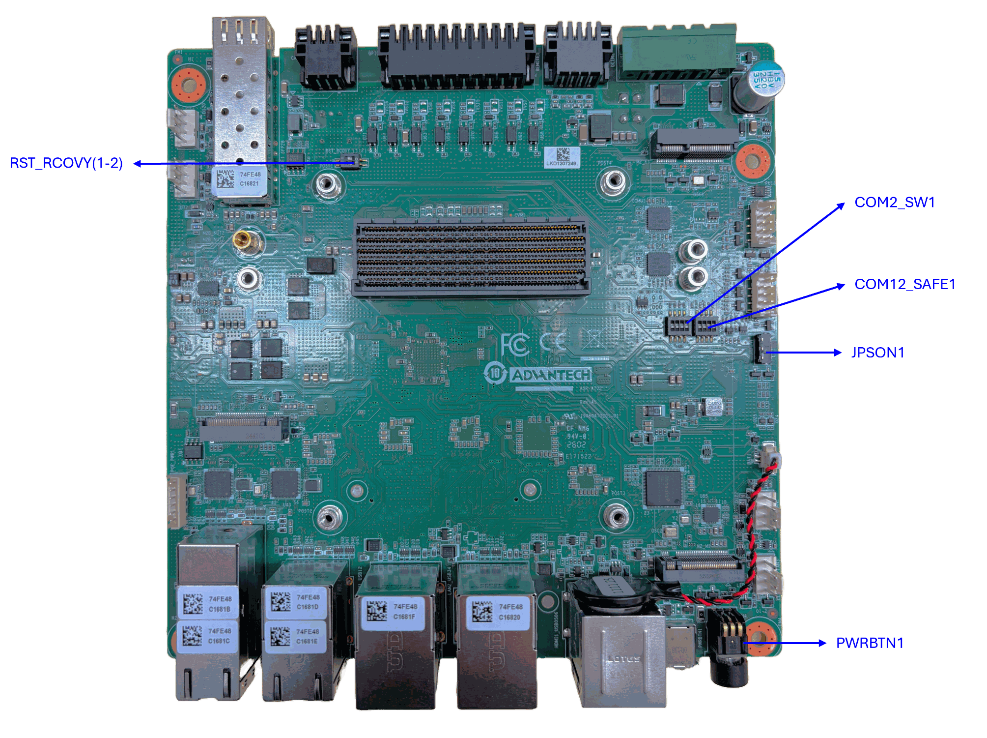
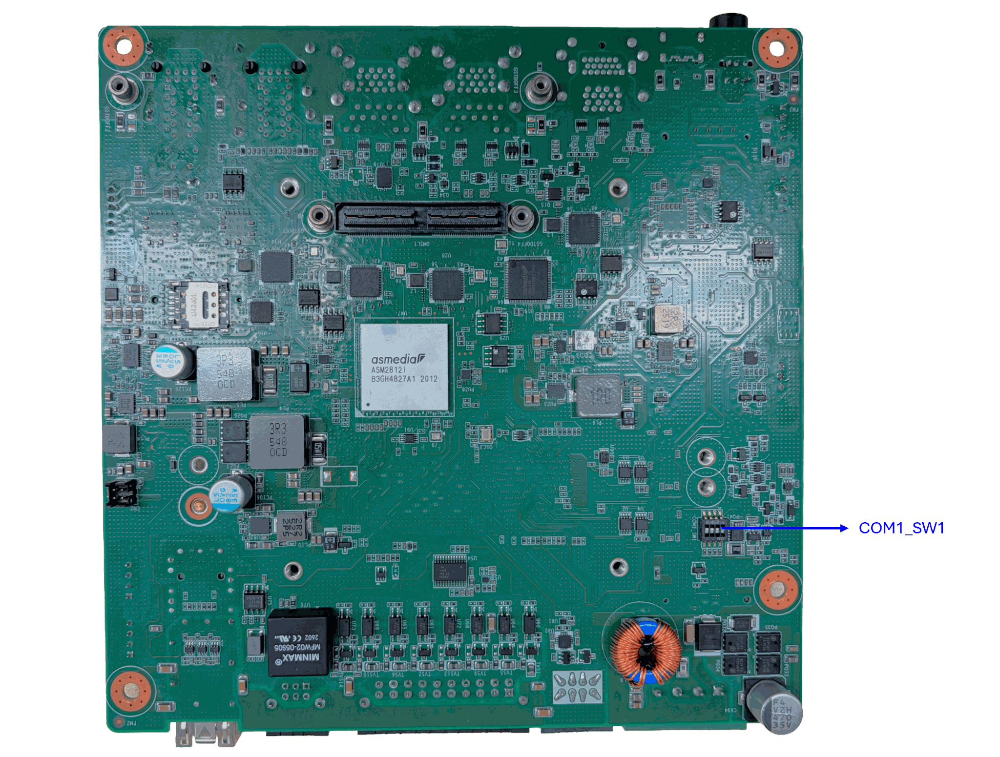
Please refer to the following images for the switch and jumper settings.
| Item | Name | Description |
|---|---|---|
| 1 | RST_RCOVY_(1_2) | System reset and system image recovery |
| 2 | COM12_SAFE1 | COM Port Failsafe Function Selection |
| 3 | COM1_SW1 | COM1 SW RS232/422/485 mode selection |
| 4 | COM2_SW1 | COM2 SW RS232/422/485 mode selection |
| 5 | PWRBTN1 | System power button |
| 6 | JPSON1 | AT/ATX mode switch |
2-3 Connector Introduction
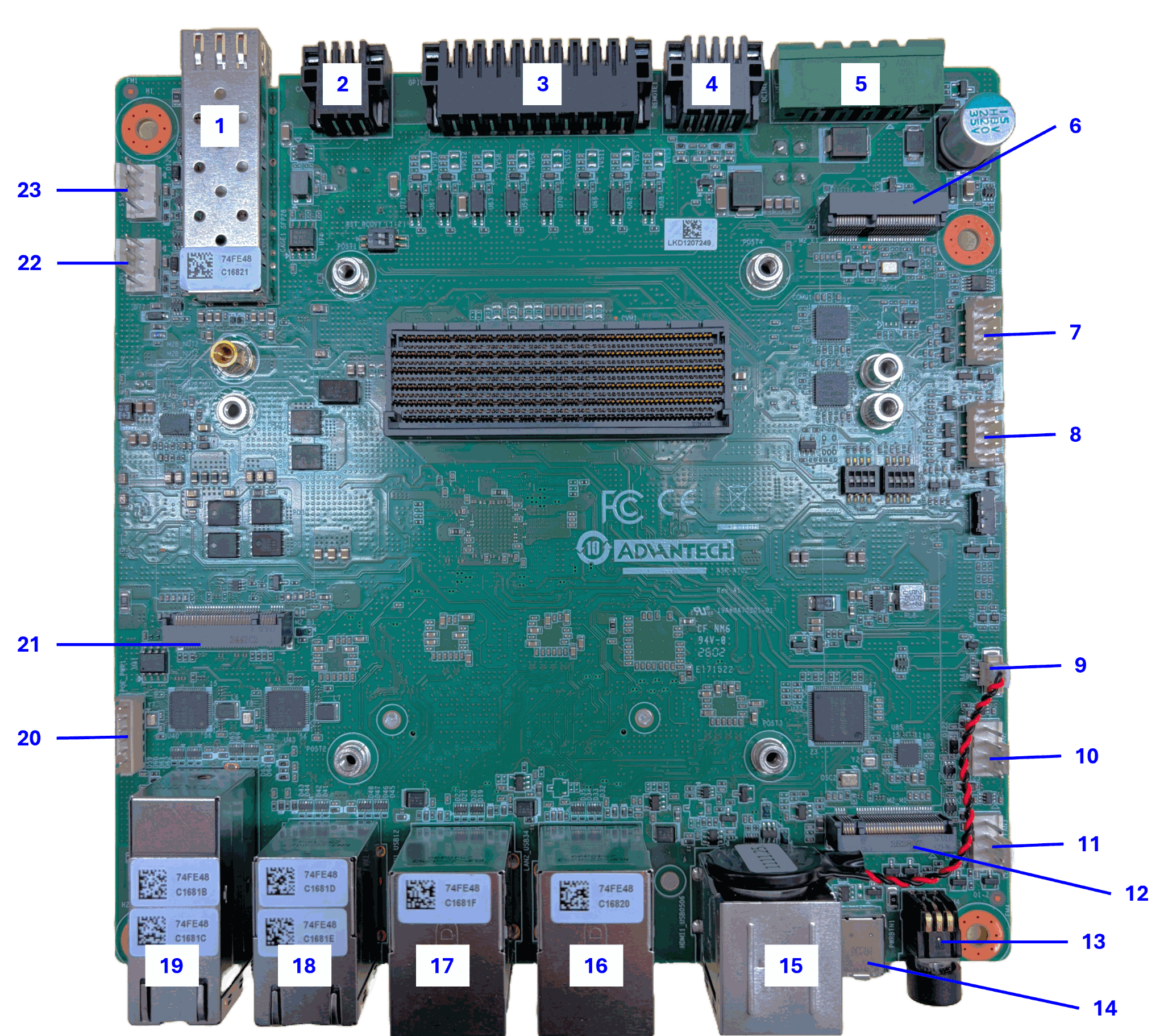
Please refer to the following images for the IO connectors, more details about the pin defination can be found in the AFE-A702 User Manual.
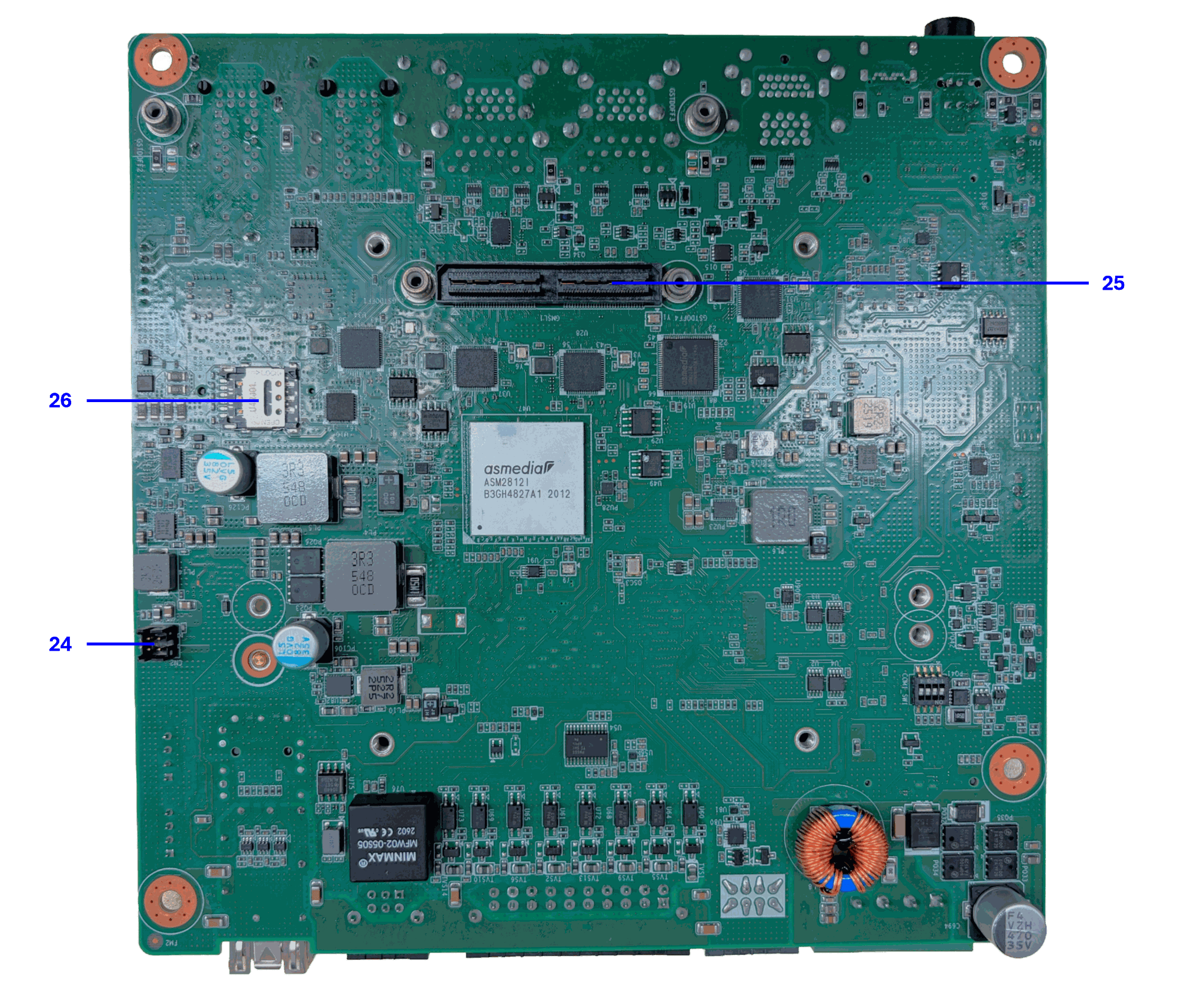
| Item | Name | Description |
|---|---|---|
| 1 | CAGE1_SFP28 | SFP28 connector |
| 2 | CAN1 | CAN BUS |
| 3 | GPIO1 | GPIO 16-bit isolation CONN I/O |
| 4 | REMOTE1 | Remote connector |
| 5 | DCIN1 | DC IN power connector |
| 6 | M2_E1 | M.2 E-Key connector |
| 7 | COM1 | COM port 1 |
| 8 | COM2 | COM port 2 |
| 9 | BAT1 | Battery connector |
| 10 | SYS_FAN2 | System fan |
| 11 | SYS_FAN3 | System fan |
| 12 | M2_M1 | M.2 M-Key connector |
| 13 | PWRBTN1 | Power button |
| 14 | OTG1 | Type-C (flash image Recovery mode) |
| 15 | HDMI1_USB0506 | HDMI + USB 3.2 Gen2 stack connector |
| 16 | LAN2_USB34 | RJ-45 + USB 3.2 Gen2 stack connector |
| 17 | LAN1_USB12 | RJ-45 + USB 3.2 Gen2 stack connector |
| 18 | LAN34 | RJ45 stack connector |
| 19 | LAN56_POE | RJ45 stack connector + POE |
| 20 | POE_PWR1 | POE power connector |
| 21 | M2_B1 | M.2 B-Key connector |
| 22 | CPU_FAN1 | CPU fan connector |
| 23 | SYS_FAN1 | System fan |
| 24 | CN2 | GMSL power connector |
| 25 | GMSL1 | GMSL MIPI-120 pins connector |
| 26 | SIM card holder | SIM card holder |
3 Operating System
3-1 BSP launcher Download
BSP launcher Download link: Download
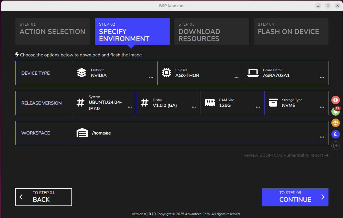
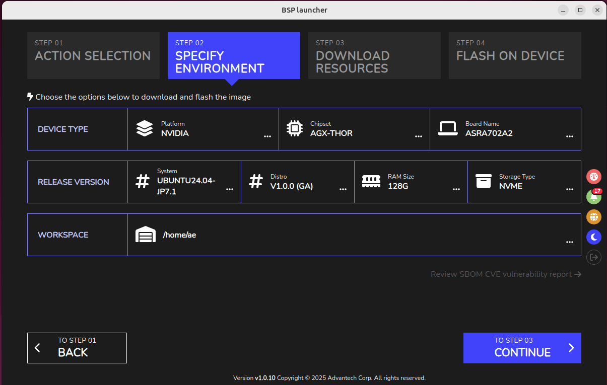
In the BSP launcher, the board name ASRA702A1 corresponds to carrier board version A101-1, while ASRA702A2 corresponds to carrier board version A101-2.
If the recovery switch is located on the top side near the SoC and CAN interface, the hardware version is A101-2.
Please be causeful when using BSP launcher to flash the BSP.
Only JetPack 7.0 and JetPack 7.2 support GMSL Cameras, please refer to 4-7 session for more details.
3-2 Image Release Note
- JetPack 7.2
- JetPack 7.1
- JetPack 7.0
| Image Version | Release Date | Image Download | BSP Download | Comment |
|---|---|---|---|---|
| JetPack7.2_v1 | 2026-08-27 | BSP-Launcher | BSP-Launcher Download | for carrier board A101-2 with AGX Thor T5000 / T4000 Ubuntu 24.04 kernel 6.8.12 |
| JetPack7.2_v0.2 (beta) | 2026-08-27 | BSP-Launcher | BSP-Launcher Download | for carrier board A101-1 with AGX Thor T5000 / T4000 Ubuntu 24.04 kernel 6.8.12 |
| Image Version | Release Date | Image Download | BSP Download | Comment |
|---|---|---|---|---|
| JetPack7.1_v1 | 2026-04-23 | BSP-Launcher | BSP-Launcher Download | for carrier board A101-2 with AGX Thor T5000 Ubuntu 24.04 kernel 6.8.12 |
| JetPack7.1_v1.0.1 (alpha) | 2026-07-31 | BSP-Launcher | BSP-Launcher Download | for carrier board A101-1 with AGX Thor T5000 Ubuntu 24.04 kernel 6.8.12 |
| Image Version | Release Date | Image Download | BSP Download | Comment |
|---|---|---|---|---|
| JetPack7.0_v1.0.1 (alpha) | 2026-07-23 | BSP-Launcher | BSP-Launcher Download | for carrier board A101-1 with AGX Thor T5000 Ubuntu 24.04 kernel 6.8.12 optimize SFP28 compliance test |
| JetPack7.0_v1 | 2025-12-17 | BSP-Launcher | BSP-Launcher Download | for carrier board A101-1 with AGX Thor T5000 Ubuntu 24.04 kernel 6.8.12 |
4 Operating Method
4-1 Account and Password
The default account and password for AFE-A702 are ubuntu.
4-2 Fan
The smart fan setting is provided as following table.
Note: The "Caution - Hot surface. Do Not Touch" warning is a default NVIDIA setting. You can adjust this setting by following the instructions in this document.
https://docs.nvidia.com/jetson/archives/r38.2/DeveloperGuide/SD/PlatformPowerAndPerformance/JetsonThor.html#bsp-specific-thermal-zones
| Temperature (℃) | Fan PWM Value | Fan RPM Value |
|---|---|---|
| 0 | 77 | 1750 |
| 50 | 77 | 1750 |
| 65 | 102 | 2300 |
| 78 | 160 | 2900 |
| 90 | 205 | 4170 |
| 100 | 255 | 5371 |
| 115 | 255 | 5371 |
4-3 Controller Area Network (CAN)
ASR-A702/AFE-A702 provides the following Controller Area Network (CAN). The CAN pin definition is shown as below.
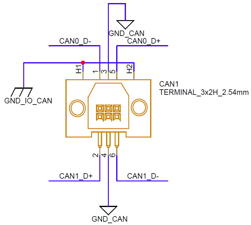
Please refer to the following commands for using CAN bus.
Connect : Hi-Hi / Lo-Lo

(CAN0 - CAN1)
$ sudo ip link set can0 up type can bitrate 125000
$ sudo ip link set can1 up type can bitrate 125000
$ sudo ifconfig can0 up
$ sudo ifconfig can1 up
$ candump can0 &
$ cansend can1 1F334455#1122334455667788
4-4 Trusted Platform Module (TPM)
ASR-A702/AFE-A702 provides TPM 2.0 module to enhance system security. Please install tpm2-tools by apt command first, and then refer to the following commands for using TPM.
$ sudo apt install -y tpm2-tools
$ sudo -s
4-4-1 File Encryption and Decryption
- Create a platform level primary key and store the content into platform_primary.ctx file.
# tpm2_createprimary -C p -c platform_primary.ctx
- Based on platform primary key, generate a public key and private key by RSA2048 encryption method.
# tpm2_create -C platform_primary.ctx -G rsa2048 -u key.pub -r key.priv
- Load the platform primary key into TPM and store the content into key.ctx file. The key.pub could be shared to others for encryption purpose, while key.priv should be kept secret.
# tpm2_load -C platform_primary.ctx -u key.pub -r key.priv -c key.ctx
- On the other devices, use key.pub to encrypt the message from msg.dat to msg.enc.
# tpm2_loadexternal -C n -u key.pub -c pub.ctx
# tpm2_rsaencrypt -c pub.ctx -o msg.enc msg.dat
- Take the msg.enc file back to AFE-A702 and decrypt the message by key.ctx. The decrypted message will be stored into msg.ptext file.
# tpm2_rsadecrypt -c key.ctx -o msg.ptext msg.enc
# cat msg.ptext
4-5 Digital Input Output (DIO)
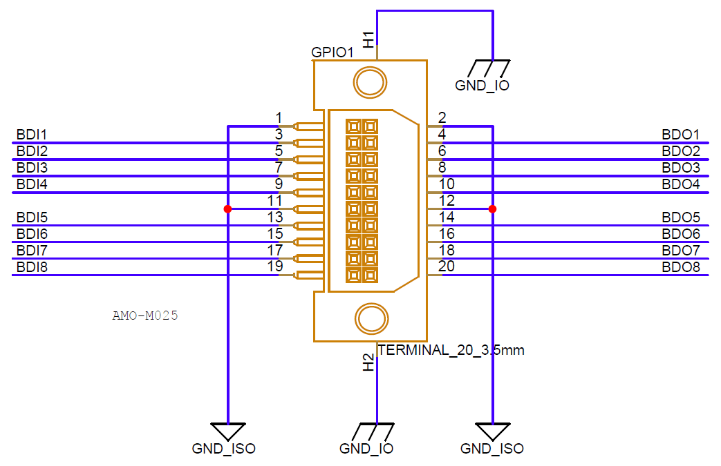
ASR-A702/AFE-A702 provides 8 bits DI and 8 bits DO, all DO are open-drain hardware design, it will require external power and pull-up resistor.
The DIO pin definition is shown as below. Please refer to the following commands for using DIO and hardware connection example.
DIO could be controlled by SUSI API, please download the SUSI installation package and refer to its Readme file for installing or Manual for developing.
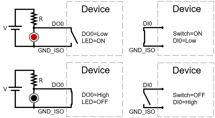
Hardware connection example for DIO are shown as below.
- When DO0 be set to low, MOSFET will be opened, current will go through LED.
- When DO0 be set to high, MOSFET will be closed, LED will be off.
- If the switch is pressed, DI0 could read the low level.
- If the switch is released, DI0 will read high level through the pull-up resistor.
4-6 Communication Port (COM)
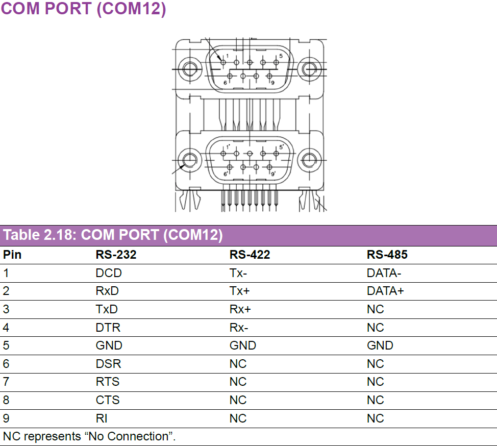
The COM pin definition is shown as below.
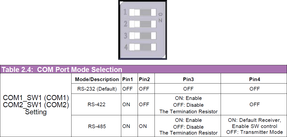
The mode selection is shown as below.
| SoC | COM1 (Flow control pin for RS-485) | COM2 (Flow control pin for RS-485) |
|---|---|---|
| AGX Thor | /dev/ttyAMA9 (663 in sysfs, 92 in gpiod) | /dev/ttyAMA10 (631 in sysfs, 60 in gpiod) |
- RS-232
- RS-422
- RS-485
RS-232 Configuration (TI_THVD4431)
RS-232 - COM1
HW Setting: COM1_SW switch is OFF-OFF-OFF-OFF, connect pin2 and pin3 on COM1.$ stty -F /dev/ttyAMA9 115200 raw -echo
$ cat /dev/ttyAMA9 & echo "1234" > /dev/ttyAMA9
RS-422 Configuration (TI_THVD4431)
RS-422 - COM1
HW Setting: COM1_SW switch is ON-OFF-OFF-OFF, connect pin1 to pin4 and pin2 to pin3 on COM1.$ stty -F /dev/ttyAMA9 115200 raw -echo
$ cat /dev/ttyAMA9 &
$ echo "ttyAMA9:echo" > /dev/ttyAMA9
RS-485 Configuration (TI_THVD4431)
RS-485 - COM1 send to COM2
Hardware control setting mode: COM1 Transmitter ON-ON-ON-OFF, COM2 Receiver ON-ON-ON-ON, connect pin1 to pin1 and pin2 to pin2 on both COM1 and COM2.$ stty -F /dev/ttyAMA9 115200 raw -echo
$ stty -F /dev/ttyAMA10 115200 raw -echo
$ cat /dev/ttyAMA10 &
$ echo "ttyAMA9:echo" > /dev/ttyAMA9
Software control setting mode: COM1 transmits to COM2, same hardware connection in above.
COM1 Transmitter: ON-ON-OFF-ON, COM2 Receiver: ON-ON-OFF-ON
Set COM1 (PM.04) as Transmitter (High)
$ echo 663 > /sys/class/gpio/export
$ echo out > /sys/class/gpio/PM.04/direction
$ echo 1 > /sys/class/gpio/PM.04/value
Set COM2 (PH.04) as Receiver (Low)
$ echo 631 > /sys/class/gpio/export
$ echo out > /sys/class/gpio/PH.04/direction
$ echo 0 > /sys/class/gpio/PH.04/value
Set baud rate and send data from COM1 to COM2
$ stty -F /dev/ttyAMA9 115200 raw -echo
$ stty -F /dev/ttyAMA10 115200 raw -echo
$ cat /dev/ttyAMA10 &
$ echo "ttyAMA9:echo" > /dev/ttyAMA9
Set COM1 (PM.04) back to Receiver (Low)
$ echo 0 > /sys/class/gpio/PM.04/value
4-7 Camera Solution
ASR-A702/AFE-A702 integrated Orbbec driver into image, please refer to the following commands for using Orbbec Gemini 335Lg. ASR-A702/AFE-A702 also supports other GMSL cameras, such as StereoLabs ZedX, please refer to the GMSL Driver for AFE-A702 for detailed instructions.
Orbbec Setup
Install the Orbbec driver:
cd /tools/orbbec/
./Install.sh
After installation, follow these steps:
- Power Down the system
- Plug in the Orbbec Gemini 335Lg camera
- Power Up the system
Load the kernel module:
sudo modprobe g300
Verify camera streaming:
gst-launch-1.0 v4l2src device=/dev/video2 ! 'video/x-raw,width=1280,height=720,framerate=30/1' ! autovideosink
4-8 Inertial Measurement Unit (IMU)
ASR-A702/AFE-A702 supports two IMU sensors, one is onboard BMI088, the other is MTi-3 which is optional.
In order to connect IMU data into ROS2, we need to install the related SDK and packages first.
$ sudo apt install -y ros-jazzy-rviz2 ros-jazzy-imu-tools ros-jazzy-imu-filter-madgwick pre-commit ros-jazzy-nmea-msgs ros-jazzy-mavros-msgs
4-8-1 BMI088
- JetPack 7.2 20260827
BMI088 driver had been integrated in JetPack 7.2 by default, please refer to the following commands for getting accelerometer and gyroscope datas from BMI088.
$ wget https://iedgeblob.blob.core.windows.net/robotic-suite-public/sensor/iio_generic_buffer
$ sudo chmod +x iio_generic_buffer
$ sudo su
# ./iio_generic_buffer -a -c 10 --device-name accelerometer -g
# ./iio_generic_buffer -a -c 10 --device-name gyroscope -g
After checking BMI088 is working, we can install its ROS2 package to visualize the data in rviz2.
$ wget https://iedgeblob.blob.core.windows.net/robotic-suite-public/sensor/xsens_bmi088-node-1.0.0-jazzy-imx8.run
$ chmod +x xsens_bmi088-node-1.0.0-jazzy-imx8.run
$ sudo ./xsens_bmi088-node-1.0.0-jazzy-imx8.run
$ source /opt/ros/jazzy/setup.bash
$ source /usr/local/Advantech/ros/jazzy/sensor_extension/ros2-imu-bmi088/install/setup.bash
$ sudo chown -R ubuntu /dev/iio:device*
$ sudo chown -R ubuntu /sys/bus/iio/devices/iio:device*/
$ ros2 run ros2_bmi088 ros2_bmi088 &
$ ros2 run imu_filter_madgwick imu_filter_madgwick_node --ros-args -p use_mag:=false &
$ rviz2
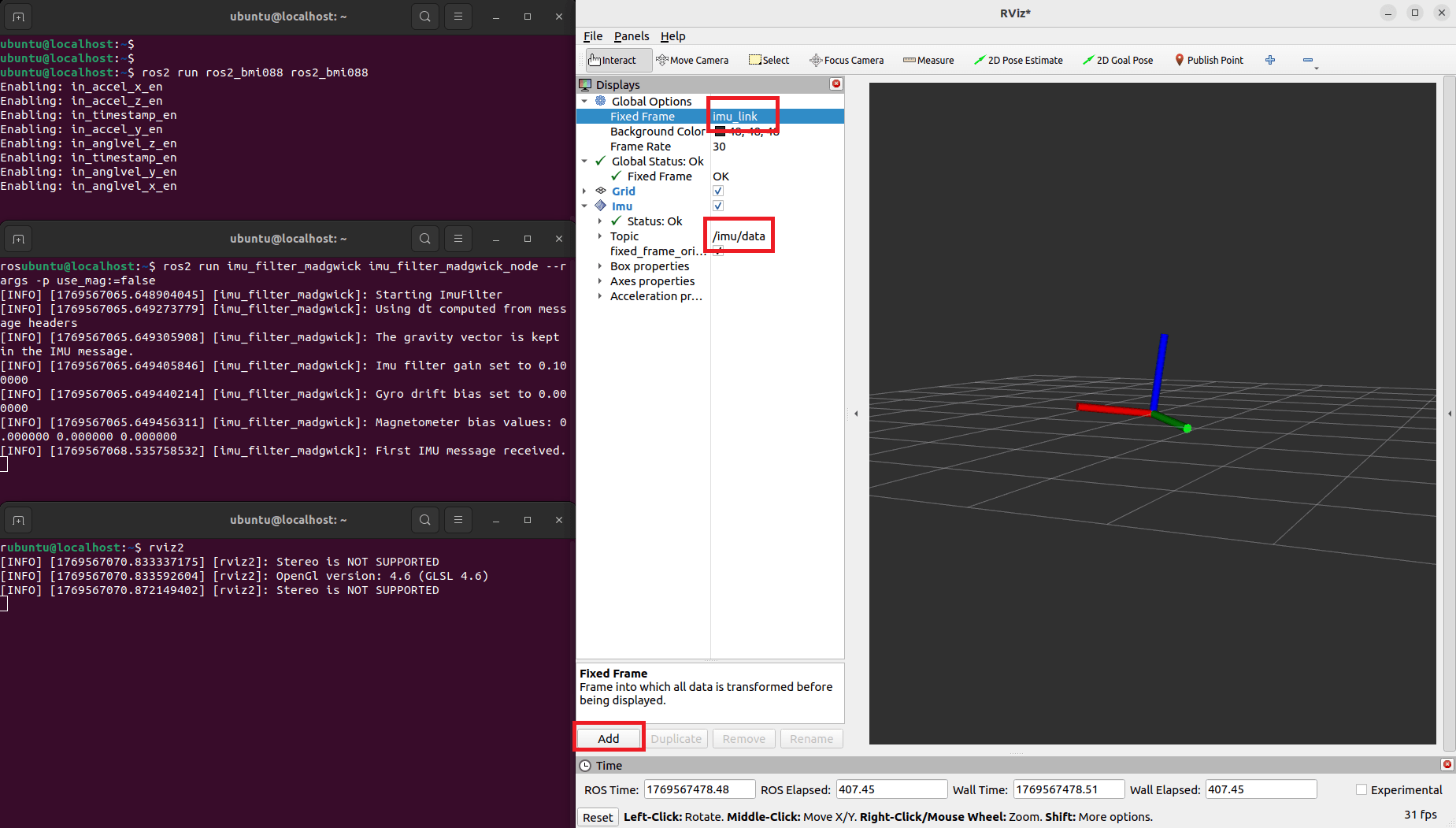
Click Add in rviz2, select By topic, add /imu/data topic , and change Fixed Frame to imu_link for visualizing the IMU data.
4-9 Wi-Fi & Bluetooth
AFE-A702 supports AW-XB560NF(AIW-169) Wi-Fi modules.
The drivers for module have been integrated into the AFE-A702 image.
4-10 LTE & 5G
AFE-A702 supports AIW-356DQ-E01 LTE/5G modules.
4-10-1 AIW-356DQ-E01
- JetPack 7.1 20260423
Run the following commands to install wvdial, set up the PPP connection, and verify external network access.
$ lsusb
$ sudo apt-get update
$ sudo apt-get install -y wvdial
$ sudo vi /etc/wvdial.conf
$ sudo wvdial &
$ ifconfig
$ ping 8.8.8.8
4-11 PPS Time Synchronization
AFE-A702 can install AIW-210XU-001 GNSS module to get PPS(pulse per second) for time synchronizing on application, PPS signal is shown as below.
Please refer to the following commands for installing GPS and time synchronzing related utility for PPS time synchronization.
$ sudo apt install -y gpsd gpsd-clients chrony
$ sudo echo -e START_DAEMON="true""\n"DEVICES="/dev/ttyACM0 /dev/pps0""\n"GPSD_OPTIONS="-n""\n"BAUDRATE="9600" > /etc/default/gpsd
$ sudo systemctl restart gpsd
$ sudo echo -e refclock SHM 0 refid NMEA offset 0.9999 delay 0.2 noselect"\n"refclock PPS /dev/pps0 lock NMEA refid PPS prefer"\n"makestep 0.001 10 > /etc/chrony
$ sudo systemctl restart chrony
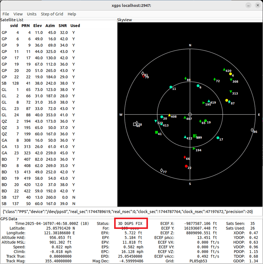
Put the GPS antenna to outdoor, and open xgps utility to check GPS status until it is 3D fixed.
Check chrony sources to see PPS is used as time source, the system time will synchronize with PPS time once the deviation threshold of time is larger than 1ms.
$ watch -n 0.1 chronyc sources