1 Product Introduction
The AFE-A503 is using the ASR‑A503 as its motherboard.
This document will share how to use AFE-A503/ASR‑A503 with Ubuntu 24.04.
Platform: Qualcomm® IQ9075M
1-1 Product Features
- Ubuntu 24.04 validation ready
- Peripheral interface function verification
- Network, display, storage, and expansion interface validation
- Suitable for robotic / edge AI application validation workflow
- Supports Advantech Robotic Suite integration workflow
1-2 Official Website
2 Hardware Interface Introduction
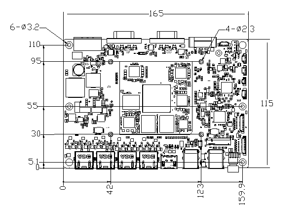
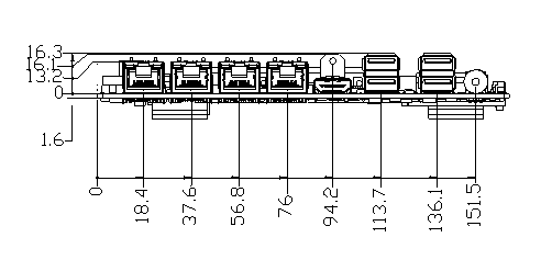
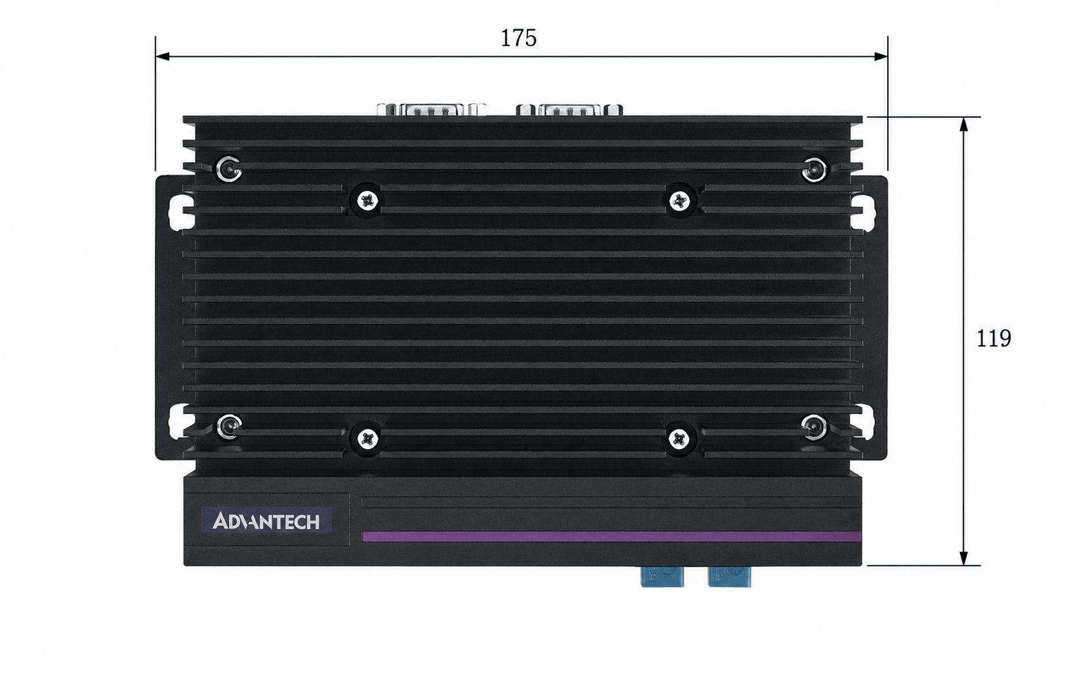
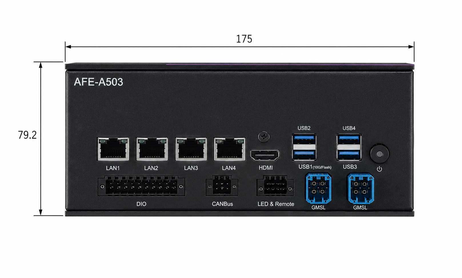
2-1 Layout and Sizes
- ASR-A503/AFE-A503 series
2-2 Switch and Connector Introduction
Please refer to the following images for the I/O connectors, more details about the pin defination can be found in the AFE-A503 User Manual.
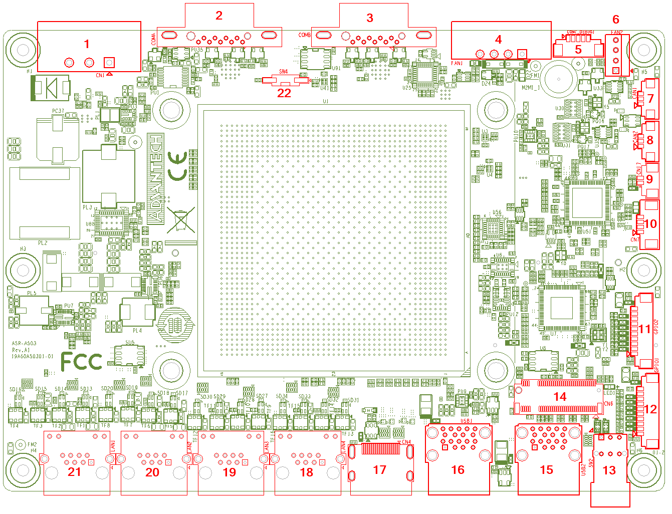
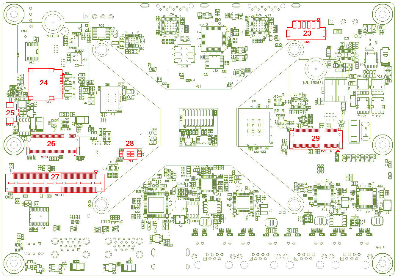
| Item | Name | Description |
|---|---|---|
| 1 | CN1 | Power Input Connector |
| 2 | COMA | COM Port Connector |
| 3 | COMB | COM Port Connector |
| 4 | FAN1 | Smart FAN External Connector |
| 5 | COMC_DEBUG | Debug Port Connector |
| 6 | FAN2 | Smart FAN Internal Connector |
| 7 | CAN1 | CAN Bus Connector |
| 8 | CAN2 | CAN Bus Connector |
| 9 | CN17 | Reset Connector |
| 10 | CN7 | I2C Connector |
| 11 | GPIO2 | GPIO Connector |
| 12 | GPIO1 | GPIO Connector |
| 13 | SW2 | Power On/Off Button |
| 14 | CN6 | M.2 Key-M Connector |
| 15 | USB2 | USB 3.2 Connector |
| 16 | USB1 | USB 3.2 Connector |
| 17 | CN4 | HDMI Connector |
| 18 | LAN4 | RJ45 Connector |
| 19 | LAN3 | RJ45 Connector |
| 20 | LAN2 | RJ45 Connector |
| 21 | LAN1 | RJ45 Connector |
| 22 | SW4 | AT/ATX Mode |
| 23 | CN5 | POE Power Connector |
| 24 | SIM1 | Nano-SIM Card Holder |
| 25 | BAT1 | RTC battery Connector |
| 26 | M2B1 | M.2 Key-B Connector |
| 27 | MIPI1 | B/B Conn. 120P |
| 28 | SW3 | USB Download Mode Select |
| 29 | M2E_CN1 | M.2 Key-E Connector |
3 Operating System
3-1 Image Download
| Image Version | Release Date | Image Download | Tag | Comment |
|---|---|---|---|---|
| AFE-A503_Ubuntu24.04-x07 | 2026-05-15 | Download | afea503a1_ubuntu24.04-x07_v1.0.0_kernel-6.8.12_iq9075.xml | Full functions |
3-2 Flashing Image
Please refer to Download BSP Launcher for detailed instructions.
Note:The image can only be flashed onto UFS, not onto M.2 NVMe.
3-3 BSP Download
Please refer to the online document for detailed instructions on how to download and build the BSP for the ASR-503/AFE-A503.
4 Operating Method
4-1 Account and Password
The default account and password for AFE-A503 are ubuntu / ubuntu.
4-2 Fan
The Fan kit Product Number is AMK-A0053,and the installation is shown as below. The smart fan setting is also provided as following table.
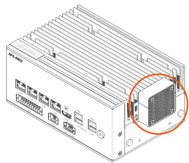
| Temp.(°C) | PWM Duty cycle(%) | Internal FAN speed(RPM) | External FAN kit speed(RPM) |
|---|---|---|---|
| 0 | 0 | 0 | 0 |
| 40 | 33 | 1980 | 3960 |
| 50 | 55 | 3300 | 6500 |
| 60 | 100 | 6000 | 11000 |
4-3 Controller Area Network (CAN)
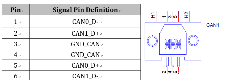
4-3-1 CAN1/2
# Connect CAN1 and CAN2
$ sudo ip link set can0 up type can bitrate 1000000 dbitrate 8000000 fd on
$ sudo ip link set can1 up type can bitrate 1000000 dbitrate 8000000 fd on
$ candump -x can1 > can1.log &
$ cat /proc/interrupts | grep spi
# Send CAN message
$ cansend can0 111FFFFF#aa.00.cc.aa.33.61.aa.ab
# Send CAN-FD message
$ cansend can0 123##1AABBCCDDEEFF00112233445566778899
$ cat can1.log
$ cat /proc/interrupts | grep spi
# spi7, 14 IRQ should be 2
4-4 Digital Input Output (DIO)
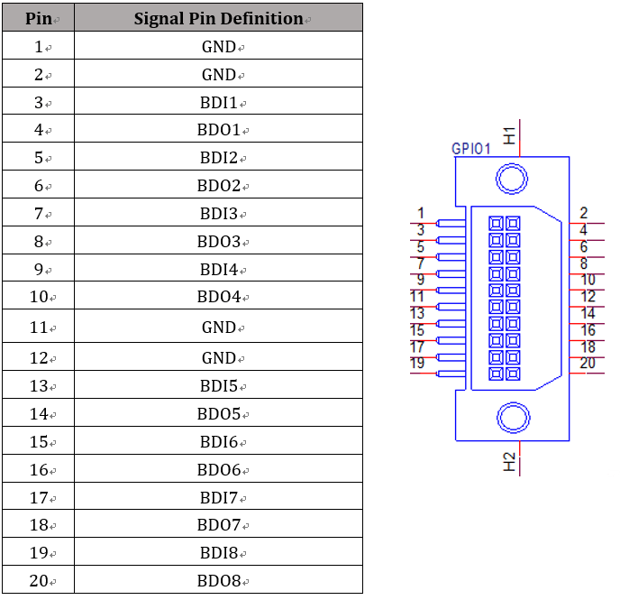
The AFE-RM06 expansion board for the AFE-A503 provides 8 bits of DI and 8 bits of DO, all DO are open-drain hardware design, it will require external power and pull-up resistor. The DIO pin definition is shown as below. Please refer to the following commands for using DIO and hardware connection example.
AFE-A503 GPIO Test
# GPIO_A_0 connect GPIO_A_1
# GPIO_A_2 connect GPIO_A_3
# ...
# GPIO_B_0 connect GPIO_B_1
# GPIO_B_2 connect GPIO_B_3
# ...
$ gpioset 5 0=0 2=1 4=0 6=1
$ gpioget 5 1 3 5 7
# 0 1 0 1
$ gpioset 5 0=1 2=0 4=1 6=0
$ gpioget 5 1 3 5 7
# 1 0 1 0
$ gpioset 5 8=0 10=1 12=0 14=1
$ gpioget 5 9 11 13 15
# 0 1 0 1
$ gpioset 5 8=1 10=0 12=1 14=0
$ gpioget 5 9 11 13 15
# 1 0 1 0
AFE-RM06 GPIO Test
# Connect RM06 on AFE-A503
# BDI1 connect BDO1
# BDI2 connect BDO2
# ...
$ i2cset -f -y 11 0x21 0x04 0xFF # Polarity invert
$ gpioset 6 8=0 9=1 10=0 11=1 12=0 13=1 14=0 15=1
$ gpioget 6 0 1 2 3 4 5 6 7
# 0 1 0 1 0 1 0 1
$ gpioset 6 8=1 9=0 10=1 11=0 12=1 13=0 14=1 15=0
$ gpioget 6 0 1 2 3 4 5 6 7
# 1 0 1 0 1 0 1 0
4-5 Communication Port (COM)
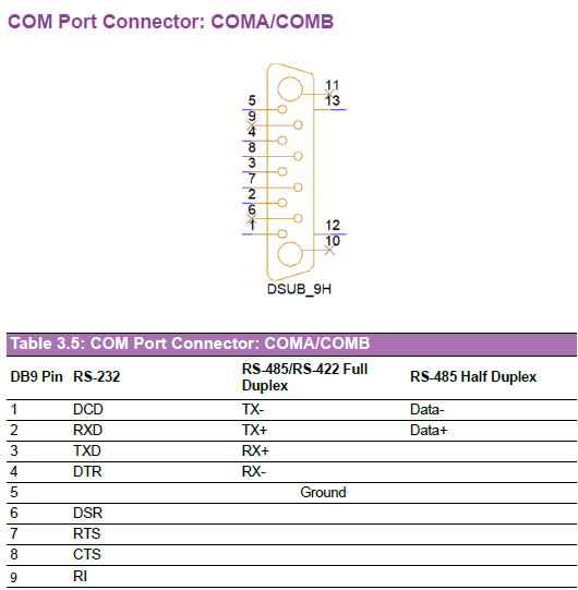
The COM pin definition is shown as below.
| COM Port | UART Device Settings | Mode Settings |
|---|---|---|
| COM1 | UART_DEV=/dev/ttyHS1 | Mode 0: 14 in gpiod Mode 1: 15 in gpiod |
| COM2 | UART_DEV=/dev/ttyHS2 | Mode 0: 18 in gpiod Mode 1: 19 in gpiod |
- RS-232
- RS-422
- RS-485
Default UART mode is RS-232.
In RS-232 mode, connect COM1 Tx to COM2 Rx and COM1 Rx to COM2 Tx.
The following commands send data from ttyTHS2(COM2) to ttyHS1(COM1),
using the echo command for transmission and the cat command for reception.
# set COM1 and COM2 be RS-232 mode (Mode0=1; Mode1=0)
$ sudo gpioset 4 14=1 15=0 18=1 19=0
$ sudo -s
$ stty -F /dev/ttyHS1 -echo -onlcr 115200 raw
$ stty -F /dev/ttyHS2 -echo -onlcr 115200 raw
$ cat /dev/ttyHS1 &
$ echo "RS-232 Test" > /dev/ttyHS2
$ killall cat
In RS-422 mode, connect COM1 Tx+ to COM2 Rx+, Tx- to COM2 Rx-, Rx+ to COM2 Tx+, Rx- to COM2 Tx-.
The following commands send data from ttyTHS2(COM2) to ttyTHS1(COM1), using the echo command for transmission and the cat command for reception.
# set COM1 and COM2 be RS-422 mode (Mode0=1; Mode1=1)
$ sudo gpioset 4 14=1 15=1 18=1 19=1
$ sudo -s
$ stty -F /dev/ttyHS1 -echo -onlcr 115200 raw
$ stty -F /dev/ttyHS2 -echo -onlcr 115200 raw
$ cat /dev/ttyHS1 &
$ echo "RS-422 Test" > /dev/ttyHS2
$ killall cat
In RS-485 mode, connect COM1 data- to COM2 data-, data+ to COM2 data+.
The following commands send data from ttyTHS2(COM2) to ttyHS1(COM1), using the echo command for transmission and the cat command for reception.
# set COM1 and COM2 be RS-485 mode (Mode0=0; Mode1=1)
$ sudo gpioset 4 14=0 15=1 18=0 19=1
$ sudo -s
$ stty -F /dev/ttyHS1 -echo -onlcr 115200 raw
$ stty -F /dev/ttyHS2 -echo -onlcr 115200 raw
$ cat /dev/ttyHS1 &
$ echo "RS-485 Test" > /dev/ttyHS2
$ killall cat
4-6 Wi-Fi & Bluetooth
4-6-1 Wi-Fi Module
AFE-A503/ASR-A503 support AIW-170(M.2 Key E) Wi-Fi module. The driver has been integrated into the Ubuntu image.
4-6-2 BlueTooth Module
AFE-A503/ASR-A503 support AIW-170(M.2 Key E) BlueTooth module. The driver has been integrated into the Ubuntu image.
4-7 4G/5G Module
AFE-A503/ASR-A503 support AIW-356(M.2 Key B)5G module. The driver has been integrated into the Ubuntu image.
4-8 GNSS
AFE-A503/ASR-A503 support AIW-210(M.2 Key B)GNSS module. The driver has been integrated into the Ubuntu image.
$ sudo apt update
$ sudo apt install -y gpsd gpsd-clients chrony
# Open xgps app and it will show GPS result
# Get latitude and longitude
# PPS GPIO increase per second
$ watch -n 1 "cat /proc/interrupts | grep pps"